5-20 Disassembly And Reassembly Procedures: Radio Reassembly – Detailed
5.7.6 Main PCB Reassembly
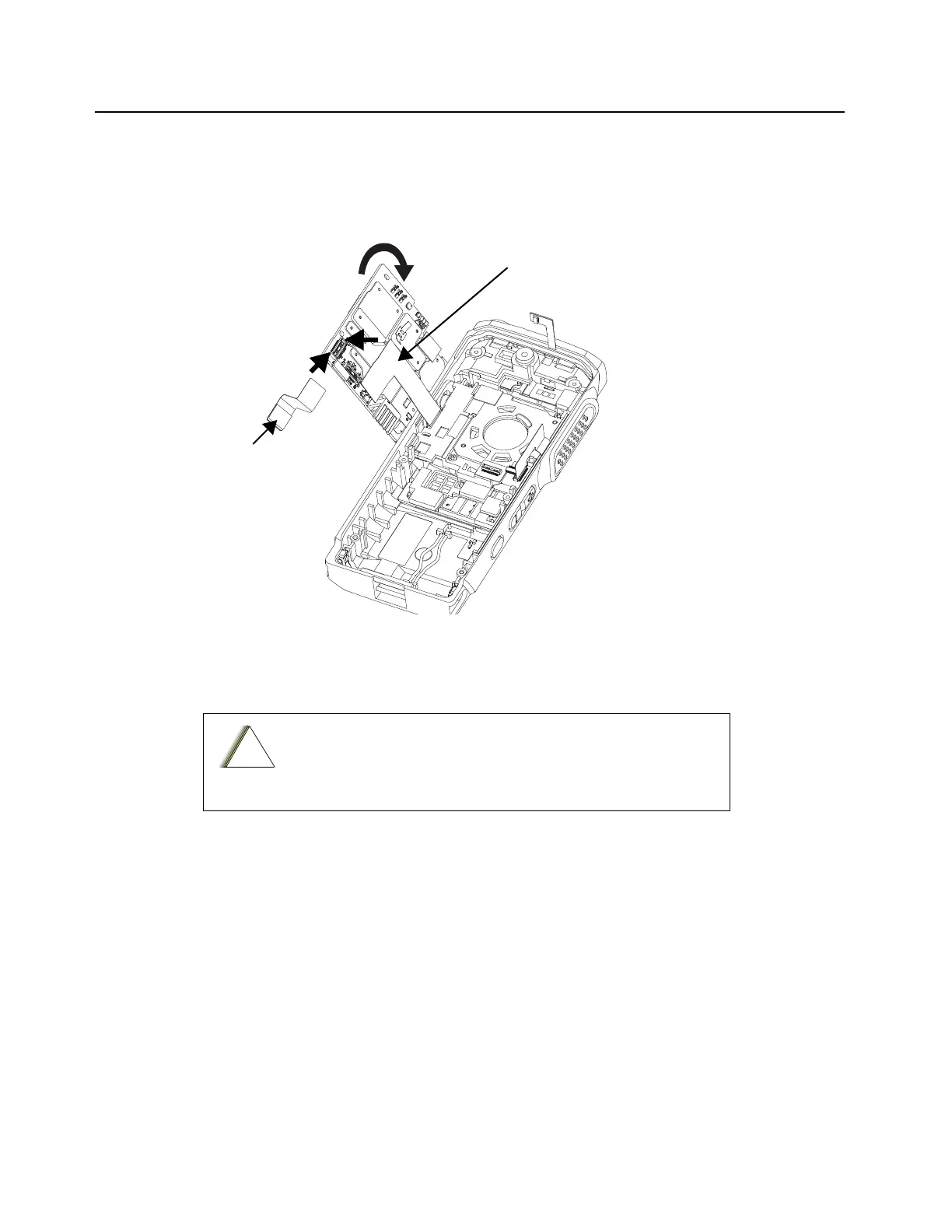
1. Attach the Audio Jack, Speaker, Micro USB, and Microphone Flex to the connector located at
the bottom side of the main PCB as shown in Figure 5-28.
2. Attach the Display Flex to the connector located at the bottom of the main PCB.
Figure 5-28. Audio Jack, Speaker, Micro USB, Microphone Flex, and Display Flex Reassembly
3. Insert the main PCB onto the internal frame.
4. Attach the Top Control Flex to the connector located at the upper side of the main PCB.
5. Attach the PTT Flex to the connector located at upper side of the main PCB.
6. Attach the Display Flex to the connector located at the LCD display module.
Only press on Poron Pad on Top Control Flex, while attaching
the flex to the connector.
Audio Jack, Speaker,
Micro USB and Microphone
Flex
Display Flex
 Loading...