- 11 -
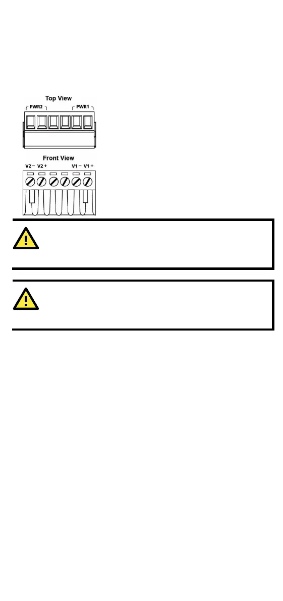
Wiring the Redundant Power Inputs
The top two contacts and the bottom two contacts of the 6-contact
terminal block connector on the EDS’s top panel are used for the EDS’s
two DC inputs. Top and front views of one of the terminal block
connectors are shown here.
STEP 1:
Insert the negative/positive DC wires into the
V
-/V+ terminals.
To keep the DC wires from pulling
loose, use
-blade screwdriver to tighten the
-clamp screws on the front of the
terminal block connector.
Insert the plastic terminal block connector
prongs into the terminal block receptor,
which is
located on the EDS’s top panel.
the EDS to the DC power inputs, make sure
the DC power source voltage is stable.
One individual conductor in a clamping point with 28
-14 AWG
wire size, and a torque value of 1.7 lb-in should be used.
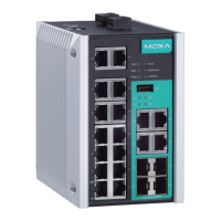
Communication Connections
The EDS-2010/2018-ML models have 10/100BaseT(X) Ethernet ports,
10/100/1000BaseT(X) Ethernet ports, and 100/1000BaseSFP.
10/100BaseT(X) Ethernet Port Connection
The 10/100BaseT(X) ports located on the EDS’s front panel are used to
connect to Ethernet-enabled devices.
Below we show pinouts for both MDI (NIC-type) ports and MDI-X
(HUB/Switch-type) ports, and also show cable wiring diagrams for
straight-through and cross-over Ethernet cables.
 Loading...