- 6 -
Do not screw the screws in all the
way—leave about 2 mm to allow room
for sliding the wall mount panel between
the wall and the screws.
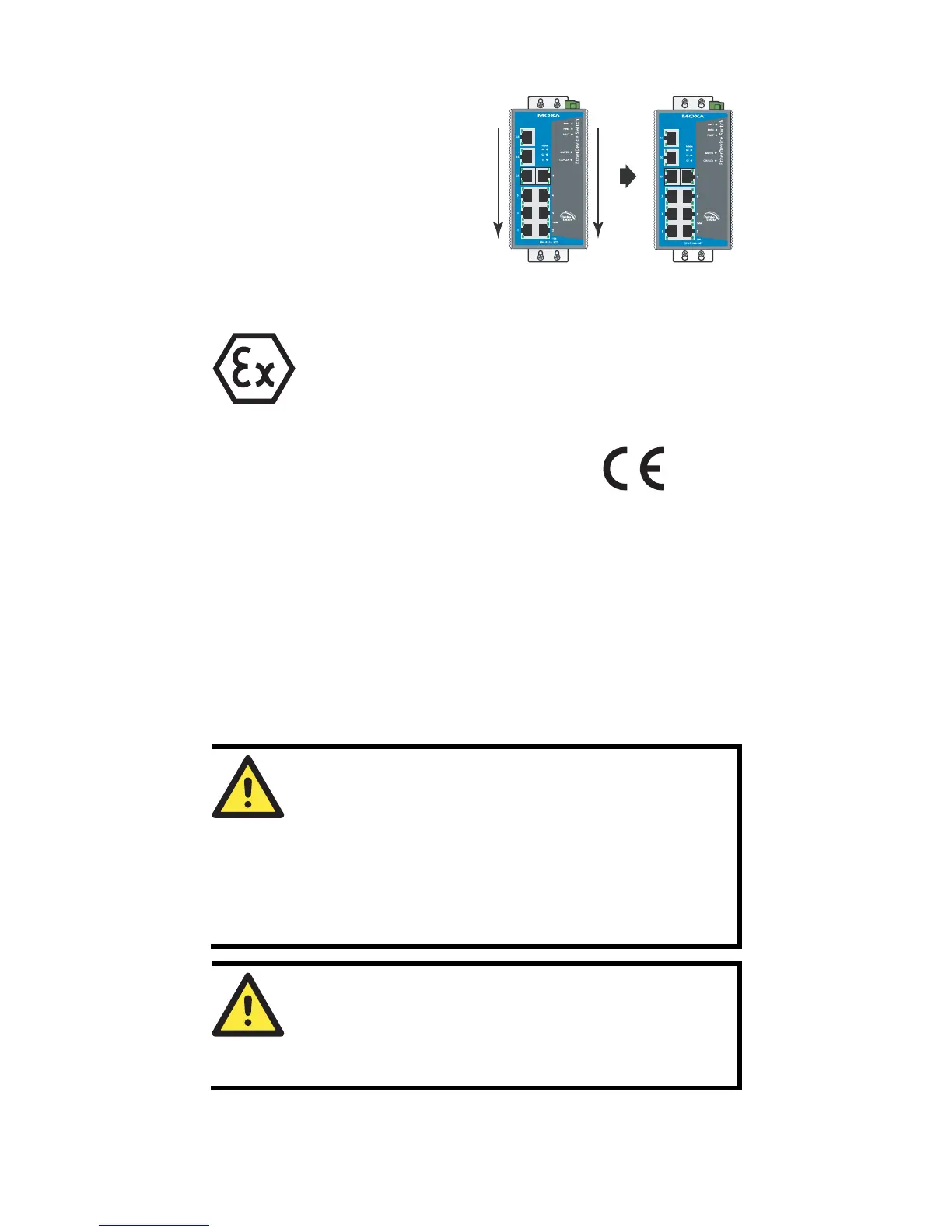
STEP 3—Once the screws are fixed to
the wall, insert the four screw heads
through the wide parts of the
keyhole-shaped apertures, and then slide
the EDS-510A downwards, as indicated
in the figure at the right. Tighten the four
screws for more stability.
II 3G
ATEX Information
1. Certificate number DEMKO 08 ATEX 0810937x
2. Ambient range (-40°C ≤ Tamb ≤ 75°C)
3. Certification string (Ex nC nL IIC T4)
4. Standards covered ( EN60079-0:2006,
EN60079-15:2005)
5. The conditions of safe usage:
y These products must be mounted in an IP54 enclosure.
y Install in an area of pollution degree 2 or less.
y Use a conductor wire of size 0.2 mm² or greater.
y PROVISIONS SHALL BE MADE, EITHER IN EXTERNAL TO
THE APPARATUS, TO PREVENT THE RATED VOLTAGE BEING
EXCEEDED BY THE TRANSIENTS DISTURBANCES OF MORE
THAN 40 %
Wiring Requirements
WARNING
Do not disconnect modules or wires unless power has been
switched off or the area is known to be non-hazardous. The
devices may only be connected to the supply voltage shown on
the type plate. The devices are designed for operation with a
Safety Extra-Low Voltage. Thus, they may only be connected to
the supply voltage connections and to the signal contact with the
Safety Extra-Low Voltages (SELV) in compliance with IEC950/
EN60950/ VDE0805.
ATTENTION
This unit is a built-in type. When the unit is installed in another
piece of equipment, the equipment enclosing the unit must
comply with fire enclosure regulation IEC 60950/EN60950 (or
similar regulation).

 Loading...