- 4 -
RS-232 CONSOLE
------
ON
OFF
MASTER
COUPLER
TURBO
RING
4
32
1
PWR2
RELAY2
RELAY1
DI2
DI1
V2-
V2+
I1
V1-
V1+
I2
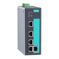
Top Panel View
1
5
6
3
2
1
Rear Panel View
2
8
7
7
4
PWR1
Top Panel:
1. Ground screw
2. RS-232 console port
3. Heat dissipation orifices
4. DIP switches for Ring Master,
Ring Coupler, and Turbo Ring
5. 6-pin terminal block for DI 1, DI 2,
and PWR 2
6. 6-pin terminal block for PWR1,
Relay 1, and Relay 2
Rear Panel:
7. Screw holes for Wall Mounting Kit
8. DIN-Rail Kit
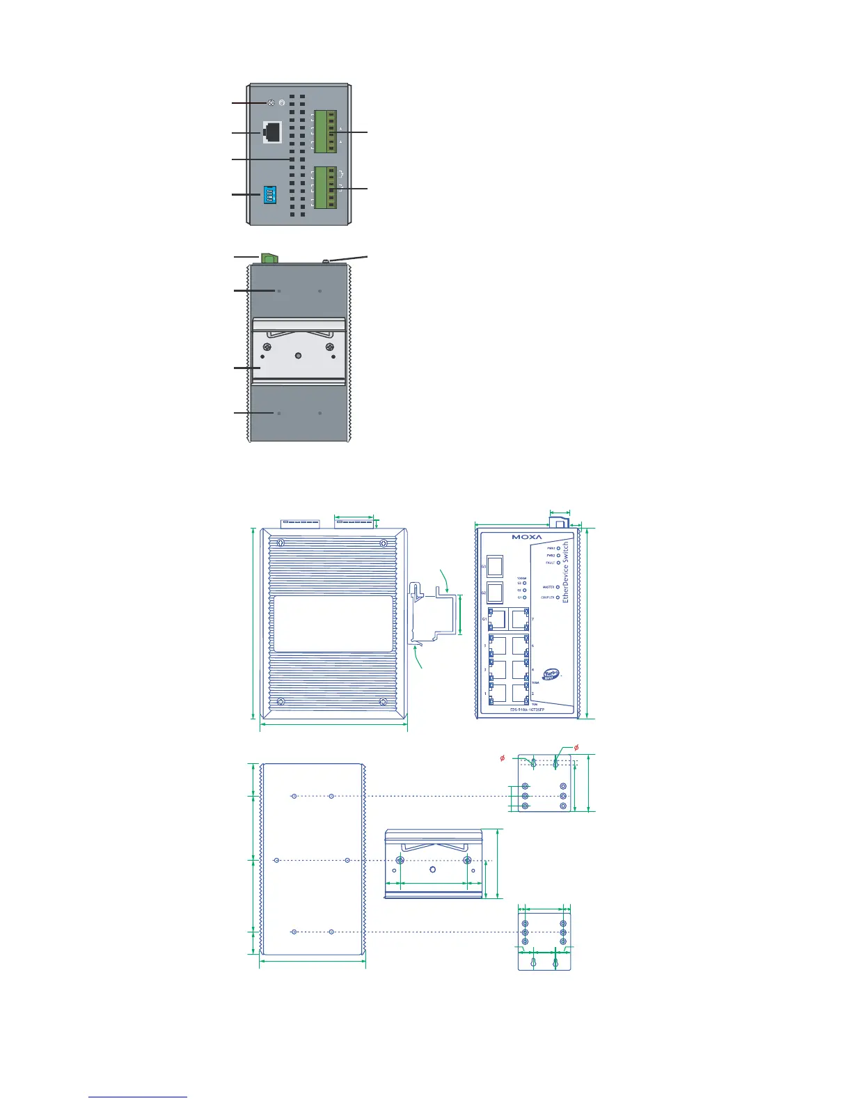
Mounting Dimensions (unit = mm)
Rear View
Side View
Front View
DlN-Rail Kit
DlN-Rail
105.00
9.00
00.53
00.531
3.42
73.9377.6465.42
00.531
Wall Mounting Kit
10
10
5
7.75
30.50
7.75
3.5
6
6
08.66
50.75
13.9 18.2 13.9
30.00
15.0
51.3
13.9
80.2
DlN-Rail Kit
7.5 55 7.5
02.72
03.84

 Loading...