mr
.
steamsteambaths
®
Installation, Operation & Maintenance Manual
7
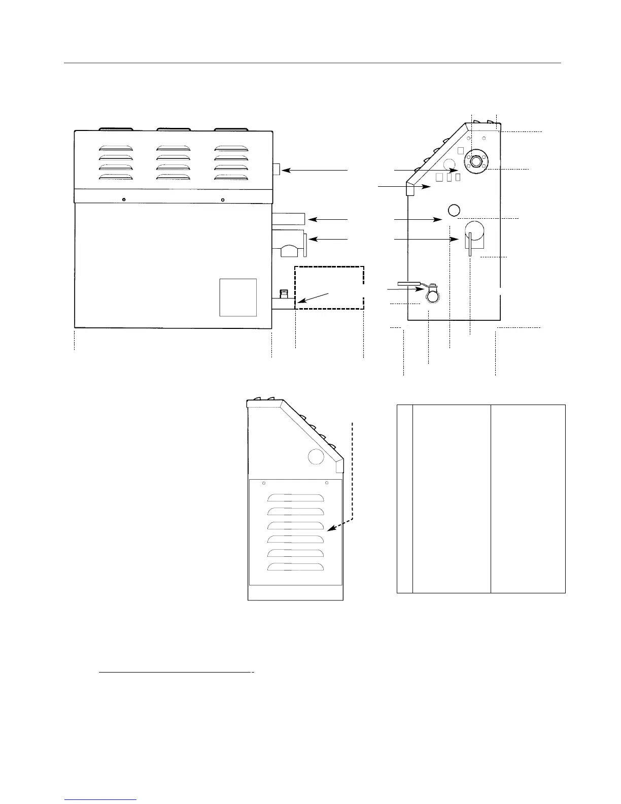
Generator Diagram
MS 65T- MS 400T MS SUPER 1T-6T
__________________________________
A 5-1/2 (140) 7-1/4 (184)
__________________________________
B 8-1/4 (210) 10 (254)
__________________________________
C 11-7/8 (302) 12-1/2 (310)
__________________________________
D 14-3/4 (375) 18-3/4 (466)
__________________________________
E 1-3/4 (45) 6 (152)
__________________________________
F 1-7/8 (48) 2-1/2 (64)
__________________________________
G 3-1/2 (89) 4 (102)
__________________________________
H 5
(127)
6
(152)
__________________________________
I 6-3/4 (171) 7-7/8 (200)
__________________________________
J 1-3/4
(45)
1-3/8
(35)
__________________________________
K 14-1/2 (368) 19-3/4 (502)
__________________________________
L 2-1/2
(64)
2-3/8
(60)
__________________________________
M 6 (152) 6-3/8 (162)
NOTES:
1.
M
=
Optional AutoFlush
2. All units in inches (MM)
3. MS Super 4T includes (2) MS Super 1T units
4. MS Super 5T includes (2) MS Super 2T units
5. MS Super 6T includes (2) MS Super 3T units
/----- F----\
/-----
L----\
/-------------------------- M -----------------------\
/------------------------------------------------------------
K-----------------------------------------------------------\
/
---------------------------------
\
/
-----------
G -
--------\
/
------------------
H
----------------
\
/-
------------------------------------
I
-
-----------------------------------
\
A
/
-----------
\
J
/
-----------------------------------------------------
\
B
/
------------------------------------------------------------------------------
\
C
/
--------------------------------------------------------------------------------------------------
\
D
W
ater Inlet
Control &
Accessory
Connections
Steam Outlet
Safety Valve
Manual Drain Valve
Optional AutoFlush
IMPORTANT NOTE:
Provide a minimum of (12) inches
at both ends and top of the steam generator or
as required for servicing. Alternately, provide
unions as required to facilitate installation and
disconnection of the steam generator.
IMPORTANT NOTE:
The minimum clearance from combustible sur-
faces is zero all around.
IMPORTANT NOTE:
Do not rough in plumbing and electrical services
based in the dimensional information provided.
Drawings are not to scale.
T
O
A
VOID EQUIPMENT D
AMA
GE DO NO
T CONNECT
POWER
SUPPL
Y DIRECTL
Y
TO ELEMENTS !!!
NOTE: FOR ILLUSTRA
TIVE PURPOSES ONLY.
Side View Showing
Element Access Panel
 Loading...