Page 29
mrcool.com
Indoor Unit Installation
Step 8: Connect Signal and Power Cables to
the Indoor Unit
In this step you will install the signal cables and
power cables to the indoor unit. The signal cable
enables the indoor and outdoor units to
communicate with one another. These cables must
be purchased separately. Use the guidelines below
for selecting the proper cables for your application.
Cable Types
• Indoor Power Cable (if applicable):
H05VV-F or H05V2V2-F
• Outdoor Power Cable: H07RN-F or H05RN-F
• Signal Cable: H07RN-F
NOTE: In North America, choose the cable
type according to the local electrical codes
and regulations.
Minimum Cross-Sectional Area of
Power and Signal Cables
Rated Current of
Appliance (A)
Nominal Cross-Sectional
Area (mm²)
Other Regions
North America
10 18
13 16
18 14
25 12
30 10
Appliance Amps (A) AWG
>3 and ≤6 0.75
1
1.5
2.5
4
6
>6 and ≤10
>10 and ≤16
>16 and ≤25
>25 and ≤32
>32 and ≤40
SELECT THE RIGHT CABLE SIZE:
The size of the power supply cable, signal
cable, fuse, and switch needed is determined
by the maximum current rating of the unit.
This rating is indicated on the nameplate,
located on the side panel of the unit. Refer to
this nameplate to select the proper cable,
fuse, and/or switch. In North America, please
choose the right cable size according to the
Minimum Circuit Ampacity (MCA) indicated on
the nameplate of the unit.
1. Prepare the cable for connection.
a. Using wire strippers, strip the rubber jacket
from both ends of the signal cable to reveal
roughly 1.57 in (40 mm) of the wires inside.
b. Strip the insulation from the ends of the
wires.
c. Using a wire crimper, crimp u-type lugs on
the ends of the wires.
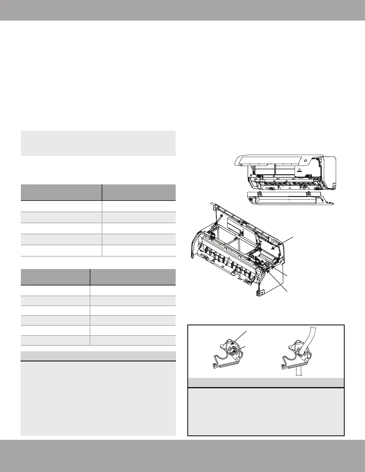
2. With the front panel of the indoor unit propped
open and the lower panel removed (completed
earlier in Step 6), open the wire box cover at the
top of the unit to expose the terminal block.
3. Then, unscrew the cable clamp below the
terminal block and place it to the side.
4. While facing the back of the unit, remove the
plastic panel on the bottom left-hand side.
5. Feed the signal cable through this slot, from the
back of the unit to the front.
Open the
front panel &
then remove
the lower
panel.
Terminal Block
Open the
Wire Cover
Cable Clamp
Rat baffle
(some units)
Knock-out
panel
• If the cable selected for the installation is
too large to fit through the hole of the unit,
remove the middle knock-out panel of the
rat baffle (Refer to Fig. 5.13).
• If the chassis or drain hose ever need to be
removed from the unit, please remove the
rat baffle first.
NOTES:
Fig. 5.12
Fig. 5.13