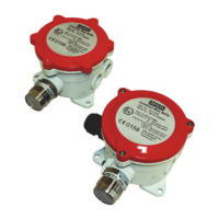
• To ensure proper function the Gas detector Series 47K must be kept dry and free of any contaminants, e.g. dust
particles and water. Regular visual checks are recommended. Any contaminants must be removed by blowing
them off with clean, oil-free compressed air or with a dry brush. Ensure that the air entrances are kept free from
any coating, e.g. paint, grease or similar.
• The sintered disc must always face downwards (±15°).
• The MSA Gas detector Series 47K must never be covered with paint, grease or similar.
• These substances prevent diffusion, of the atmosphere to be monitored, to the sensing elements.
3.4 Recommended Torque and Terminal Sizes
Cable gland size Connection thread Pressing screw Terminal sizes
M25 x 1,5 3,0 Nm 2,0 Nm 7–12/10–17* mm
* To be able to use size M25 x 1,5 for terminal sizes 10–17 mm, remove the small sealing ring.
3.5 Electrical Connection to the Control Unit
3.5.1 Junction Box Terminals
Screw terminals: cross section 0,5–2,5 mm
2
, screw torque 0,55 Nm ± 0,05 Nm
Spring terminal: cross section 0,5–1,5 mm
2
3.5.2 Maximum Cable Length
The maximum cable length depends on the maximum permissible load, the cross section of the conductor and the
conductor material.
The maximum permissible load [loop resistance] is 36 ohms for the MSA Control units SUPREMA [for MSA Control unit
9010/9020 refer to the control unit manual].
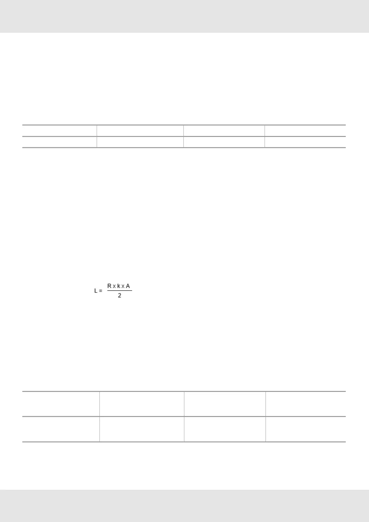
Maximum cable length:
L = cable length in metres [loop]
R = maximum permissible load in ohms
A = cross sectional area of conductor in mm
2
k = conductivity of copper = at 20 °C [1/Resistivity]
Example: R = 36 ohms, A = 0.75 mm
2
, k = 56 m ohms
-1
mm
-2
L = 36 x 56 x 0.75/2 = 756 m
Wire Cross Section Maximum Load
[max. cable resistance]
Maximum Length Remarks
0.75 mm
2
1.5 mm
2
36 Ohm
36 Ohm
750 m
1,500 m
Screened cable is required.
For detailed information refer to the relevant MSA controller manual.
11 Series 47K GB
3 Installation
 Loading...