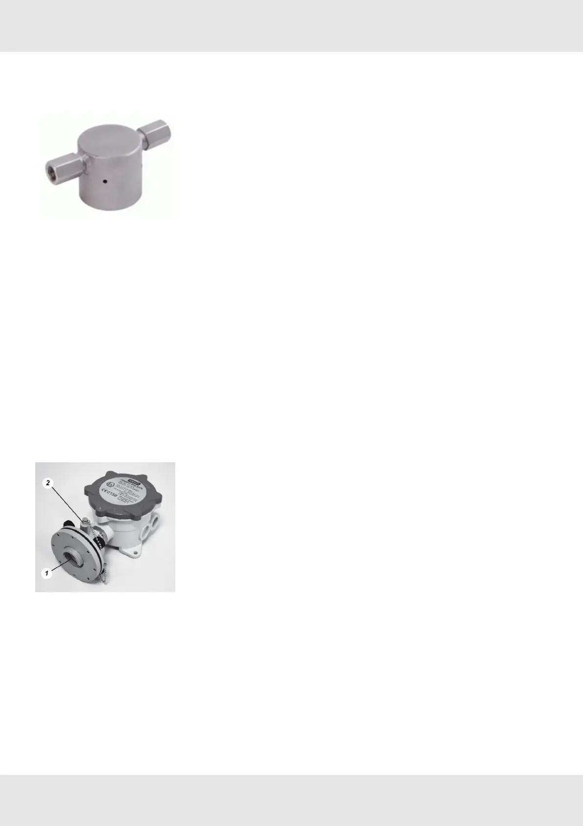
6.3 Flow Through Adapter/ Pump Adapter
Figure 1 Flow Through Adapter
The flow through adapter is for use with a pumped sampling system.
Pipe connection : 1/8” NPT
Gas flow rate : 1.0 l/min ±20%
Using the Flow Through Adapter will extend the response time, depending on the gas flow rate and the length of the
tubes. Only the pressure range from 800 to 1200 hPa is allowed. The gas flow has to be monitored.
6.4 Duct Mount Flange
Gas monitoring in air ducts can be performed by means of this duct mount flange. When installing it the direction of flow
inside the duct must be towards the baffle as shown in the photograph.
The sensor can be calibrated via the gas calibration port, provided the duct is free of all gases to which the sensor will
respond. If the duct cannot be gas freed, the sensor has must be removed form the duct during calibration.
The calibration port must be sealed again with the locking cap after calibration has been carried out.
Figure 2 Duct Mount Flange
1. Flow 2. Gas calibration point
In this Picture will be the flow from the bottom up.
You should calibrate with the calibration port only during air velocity < 5 m/s for Series 47K-PRP and 47K-HT-PRP in the
air duct.
The response times given in Chapter 2.3 are for an air velocity of 20 m/s.
Doubling of the response time has to be expected for an air velocity of 0.5 m/s.
19 Series 47K GB
6 Accessories
 Loading...