Gas flow rate : 1.0 l/min
Stabilization time : depending on gas type between 2 and 4 min
CAUTION!
Use span gas with a concentration of approximately 50% of the measuring range. In no case should the span gas
concentration be less than 25% of the full scale value of the measuring range.
If possible, the span gas [the gas used to calibrate the sensor] and the measurement gas [the gas to be monitored]
should be identical. If this is not the case and a reference gas is used, the response factor of the gas used must be
known.
Failure to follow these cautions can result in minor or moderate injury.
5.1.3 Calibration with Accessories
Calibration of Gas detectors used with duct mount flange, flow through adapter or weather protection cap should be
carried out as described above using the particular gas inlets of the accessories.
Gas flow rate : 1.0 l/min
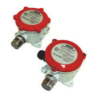
5.2 Sensor Replacement
CAUTION!
In a hazardous area, ensure all necessary precautions are taken before opening the junction box. Replacement of the
sensor or other parts should only be carried out by suitably qualified personnel.
Failure to follow this caution can result in minor or moderate injury.
After checking if it is possible to carry out operation, according to the type of danger in the area where the gas detector is
installed, proceed as follows:
1. Disconnect the power supply to the gas detector at the Control unit.
2. Remove the sensor junction box cover.
3. Note the wire colours and numbering of the terminal board and disconnect the sensor wires.
4. Unscrew the sensor from the junction box.
5. Screw the new sensor into the junction box using the correct size of tool across the hexagon flats.
6. Connect the sensor wires to the terminal block and ensure they are connected to the correct terminals.
Refer also to the wiring diagram in Section 10 .
Close the sensor junction box cover and ensure that the gas detector is in compliance with all relevant safety regulations
and directives.
5.3 Series 47K-PRP and Series 47K-HT-PRP
For the gases or vapours shown in the tables of Section 5.3.1 and 5.3.2 the response curves have been tested
according to EN 60079-29-1. If the LEL of a substance was not listed in EN 60079-20-1, the LEL has been taken from
the Chemsafe data base [Dechema, Frankfurt]. Due to legal requirements other locally used LEL values might be
mandatory.
It is highly recommended that the gas detector is exposed to clean air when calibrating the zero and a mixture of the
target gas in air with a concentration of approximately 50% LEL. Other gases/ vapours on request.
If calibration with the target gas is not possible a reference calibration can be performed with 0,85 vol% Propane C
3
H
8
in
air and using the relative response data given in the table of Section 5.3.1 and 5.3.2 . These values are only valid for
15 Series 47K GB
5 Maintenance and Service
 Loading...