Hardware Setup
2-15
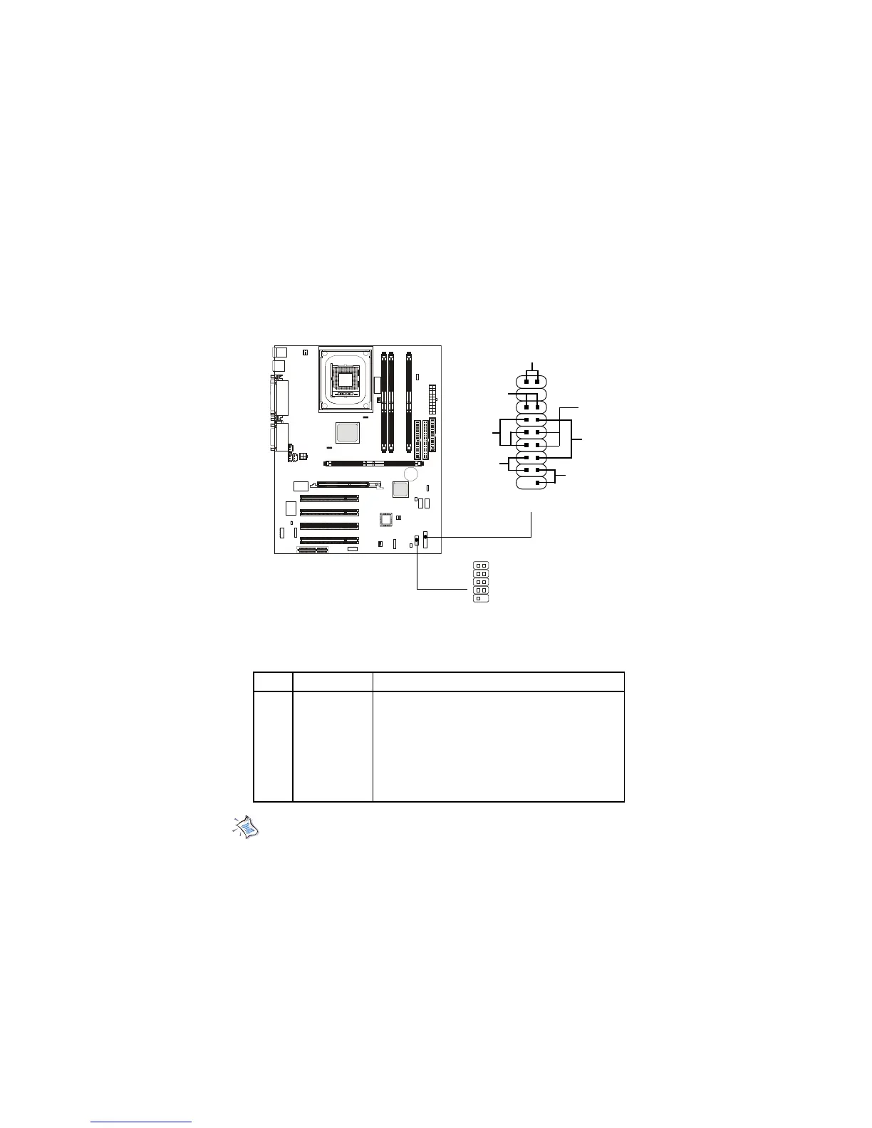
Front Panel Connector: JFP1 or J23 (Optional Intel spec)
This connector is for electrical connection to the front panel switches
and LEDs.
PIN SIGNAL DESCRIPTION
1 HD_LED_P Hard disk LED pull-up
2 FP PWR/SLP MSG LED pull-up
3 HD_LED_N Hard disk active LED
4 FP PWR/SLP MSG LED pull-up
5 RST_SW_1 Reset Switch 1
6 PWR_SW_P Power Switch high reference pull-up
7 RST_SW_2 Reset Switch 2
8 PWR_SW_N Power Switch low reference pull-down to GND
9 RSVD_DNU Reserved. Do not use.
J23 Pin Definition
JFP1
Power
Switch
Power
LED
+
Reset
Switch
HDD LED
+
Speaker
Buzzer
(short pin)
14
15
Keylock
1
10
J23
(Optional Intel spec)
1
2
Note: The RST_SW_1 and RST_SW_2 signals should be connected to
the Reset Switch independently from other signals (HDD, PWR, GND,...)
on the J23 Front Panel Connector.