CARBURETOR ADJUSTMENT
WARNING: If any adjustments are
made to the engine while the engine
is running (e.g. carburetor), keep
clear of all moving parts. Be careful
of heated surfaces and mufflers.
Minor carburetor adjustment may be required
to compensate for differences in fuel, tempera
-
ture, altitude and load.
Refer to the separate engine manual packed
with your unit for carburetor adjustment infor
-
mation.
NOTE: Failure to comply with suggested
maintenance and lubrication specifica
-
tion will void warranty.
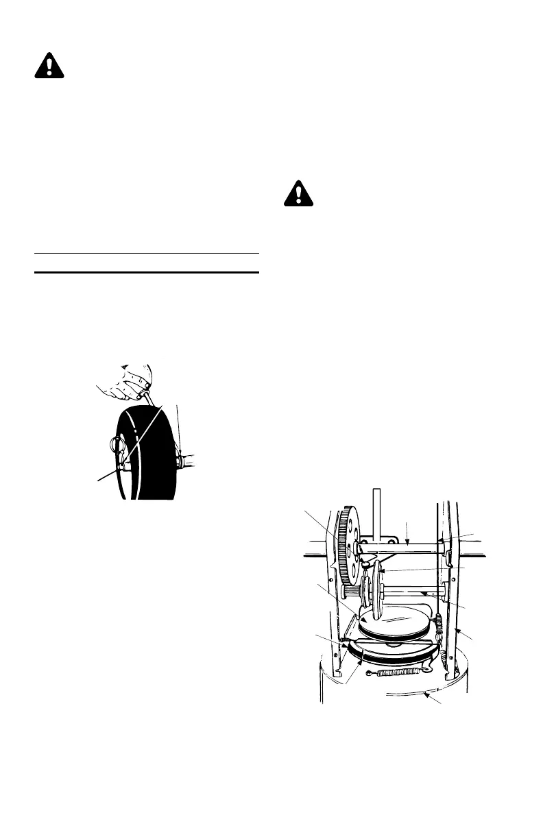
LUBRICATION
WHEELS
Oil or spray lubricant into bearings at wheels at
least once a season. Remove wheels, clean
and coat axles with a multi-purpose automotive
grease. See figure 17.
DRIVE AND SHIFTING MECHANISM
Remove rear cover. Oil any chains, sprockets,
gears, bearings, shafts, and shifting mechanism
at least once a season. Use engine oil or a
spray lubricant. Avoid getting oil on rubber fric
-
tion wheel and aluminum drive plate.
GEAR BOX
The worm gear box has been filled with grease
at the factory. If disassembled for any reason,
lubricate with 1.5 ounces of Shell Alvania
grease EPR00, part number 737-0168. Before
reassembling remove old sealant and apply
“Loctite 5699" or equivalent.
CAUTION: Do not overfill the gear box, damage
to the seals could result. Be sure the vent plug
is free of grease in order to relieve pressure.
CHUTE CRANK WORM
The worm gear on the chute direction crank
should be greased with multi-purpose automo
-
tive grease.
AUGER SHAFT
Remove auger bolts on auger shaft. Oil or
spray lubricant inside shaft. See figure 19.
ENGINE
Refer to engine manual for engine lubrication
instructions.
WARNING: When following instruc
-
tions in separate engine manual for
draining oil, be sure to protect frame
to avoid oil dripping onto transmis
-
sion parts.
Gear Shaft
Lubricate the gear (hex) shaft with a light
weight cold weather lubricant at lease once a
season or after every 25 hours of operation.
IMPORTANT: Keep all grease and oil off of the
rubber friction wheel and aluminum drive plate.
If for any reason your transmission was disas
-
sembled and the drive cable disconnected,
make sure when reassembling to route the ca-
ble correctly before reconnecting to support
bracket. See figure 18.
Models with 13” and 15” wheels: Pass the
drive cable between the drive shaft and the
gear shaft.
Models with 16” wheels: Pass the drive ca-
ble under the drive shaft and the gear shaft.
13
FIGURE 17
Oil Bearings
Or Spray Lubricant
Axle
FIGURE 18
Friction
Wheel
Disc
Auger
Belt
Friction
Wheel
Auger
Pulley
Shift
mechanism
Drive
Shaft
Drive
cable
Auger
Housing
Gear
Shaft
Frame