CYLINDER HEAD
65
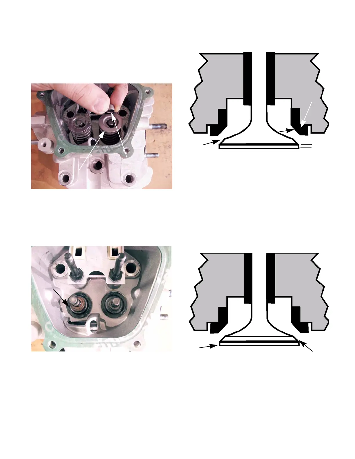
NOTE: The exhaust valve has a cap called an
“adjuster” on it. The cap needs to be pulled off
before the keeper can be removed.
See Figure 9.11.
4. Lift the springs off of the valve stems.
5. Slide the valves out of the cylinder head.
NOTE: Only the intake valve has a valve guide
seal.
See Figure 9.12.
Figure 9.11
Secondary valve
keeper
Valve keeper
Figure 9.12
Seal
6. Inspect the valve seat. See Figure 9.13.
• Valve seats are 45 degrees, with a 31 degree
topping cut and a 61 degree narrowing cut.
• Seat width should be .028”-.035” (0.7 - 0.9mm)
with a margin of .024” (0.6mm) on the exhaust
valve and .027” (0.7mm) on the intake valve.
NOTE: The valve seat can be ground to clean it
up as long as the finished seat is within the toler
-
ances listed above.
7. Inspect the valve stem. See Figure 9.14.
Figure 9.13
Seat angle is 45
o
.028-.035”
Seat
contact
margin
Figure 9.14
45
o
Inspect for a
burnt edge
 Loading...


