THE FUEL SYSTEM AND GOVERNOR
32
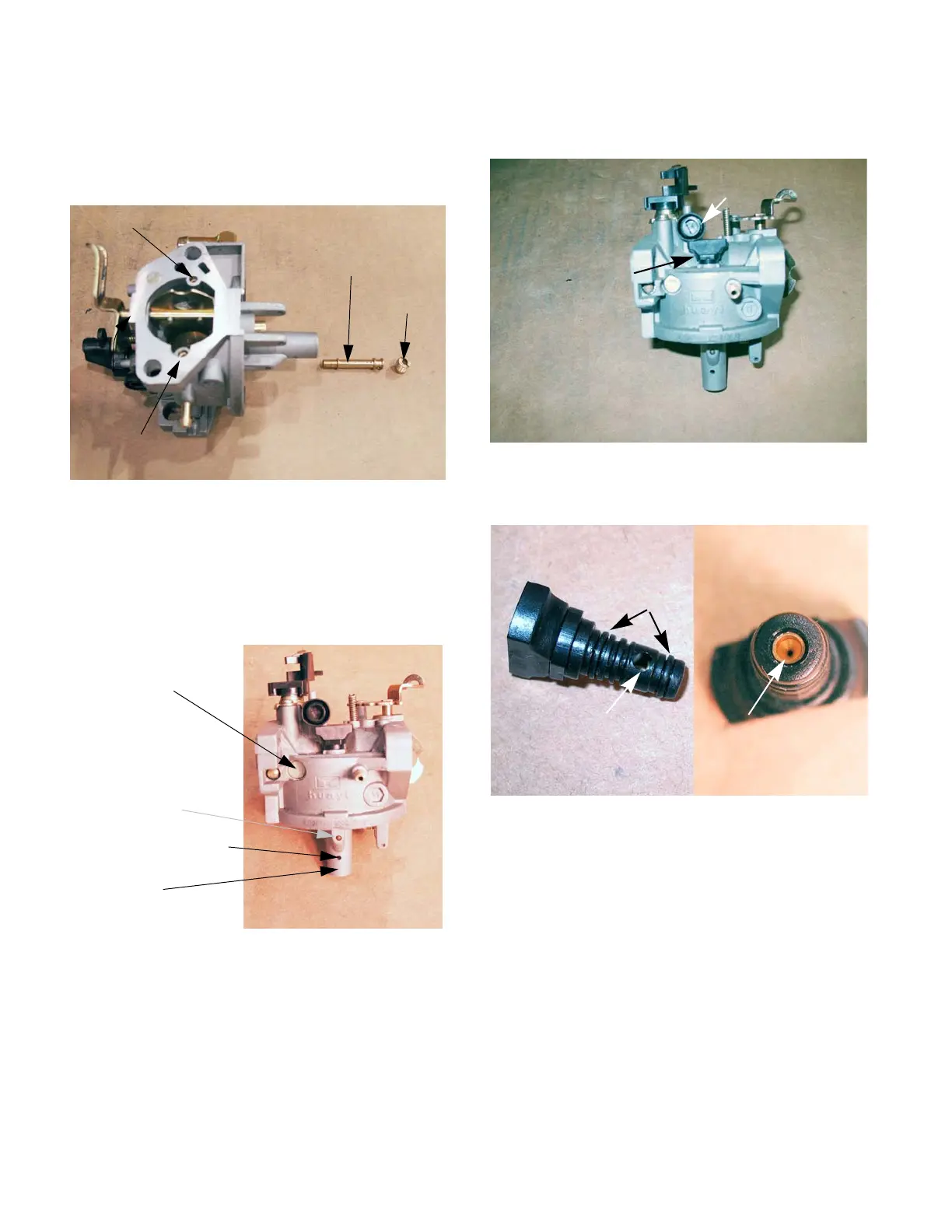
NOTE: The main jet secures the emulsion tube
in the central column of the carburetor.
See Figure 4.16.
10. The throttle stop screw has a large pliable lip
around the head of the screw. That lip secures a
metering plug for the pilot and transition ports.
Remove the screw to reach the plug.
See Figure 4.17.
11. Carefully pry out the metering plug using a small
screwdriver.
See Figure 4.18.
12. Examine the metering plug: See Figure 4.19.
• Fuel, drawn from the central column via the long
fuel feed leg, is metered by the brass orifice in
the tip of the metering plug.
• Air, drawn from the emulsion air port, is metered
by the size of the brass orifice at the entrance to
the port.
• The fuel and air that feed the pilot and transition
ports are mixed at the metering plug.
• The metering plug creates a small venturi. The
pressure drop of the air passing through the
metering plug draws the fuel into the passage to
the pilot and transition ports, in an emulsified
mixture.
Figure 4.16
Emulsion air port: main jet
Emulsion air port: pilot jet
Emulsion tube
Main jet
Figure 4.17
Welch plug
Fuel feed leg
on central
column for pilot
and transition
shot plug in feed bore
Fuel port to
central column
Figure 4.18
Throttle stop
screw
Metering
plug
Figure 4.19
Air passage
O-rings
End view
Fuel metering orifice
 Loading...