THE FUEL SYSTEM AND GOVERNOR
33
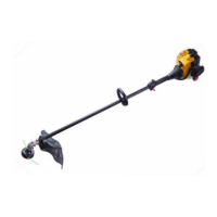
NOTE: The pilot screw regulates how much of
this pre-mixed fuel/air emulsion is allowed to
enter the throat of the carburetor, to atomize
down-stream of the throttle plate. On current
production units, it is set at the factory and the
screw head is removed.
See Figure 4.20.
NOTE: The transition ports are fixed. They are
drilled into the throat of the carburetor, down-
stream of the venturi. They lie behind the brass
welch plug near the pilot screw.
13. Soak the Carburetor body in a suitable solvent
until clean.
NOTE: Ultrasonic cleaning using a suitable
water/detergent mixture will clean carburetors
safely and effectively.
14. Rinse it thoroughly.
15. Dry the carburetor body using compressed air.
16. Reassemble the carburetor and install it by fol-
lowing steps 1-8 in reverse order.
Figure 4.20
Transition ports Pilot port
Pilot screw
(before head
is removed)
17. Start the engine and check the idle RPM using a
tachometer.
18. Check the top no load speed of the engine.
NOTE: The top no-load speed of the engine is
3500 RPM’s
+ 100.
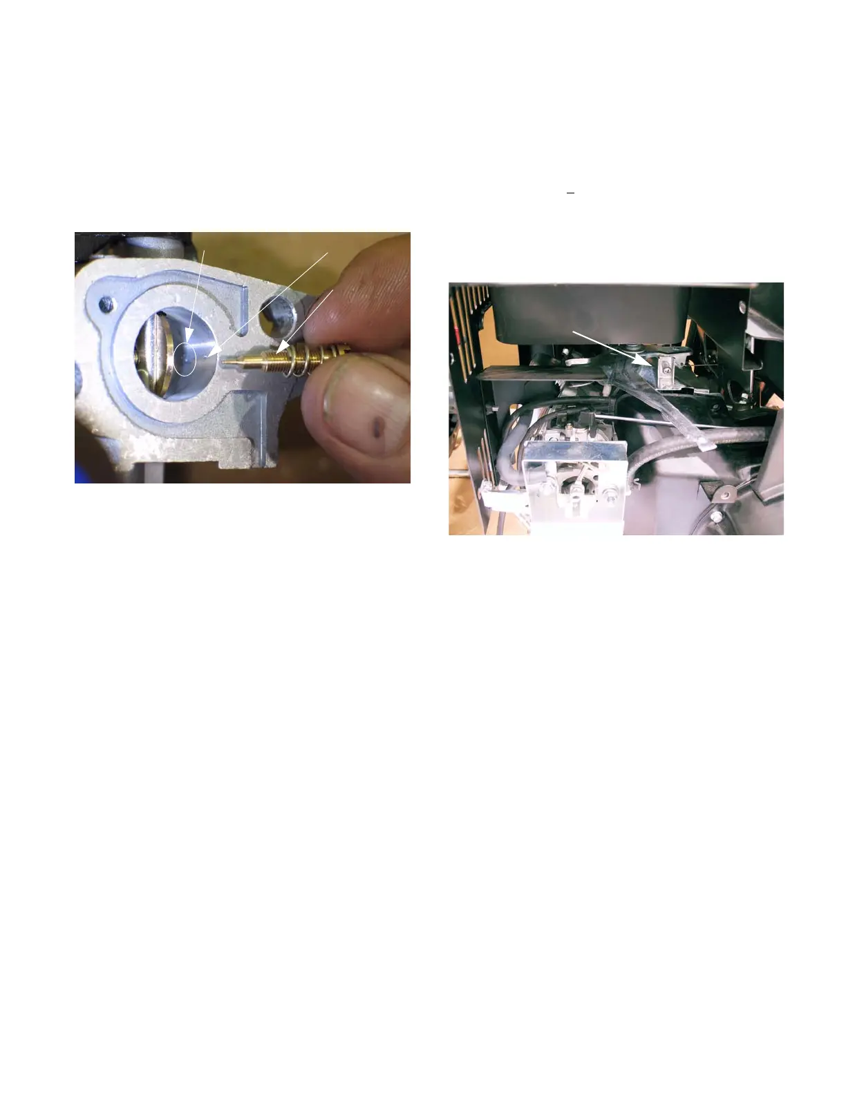
19. The top no-load speed is easily adjusted by
tightening/loosing the speed adjustment screw.
Tighten the screw to decrease speed and loosen
it to increase speed.
See Figure 4.21.
Figure 4.21
Adjustment screw
 Loading...