Introduction
15
75 series engines
6. Check valve lash between each valve stem and
rocker arm using a feeler gauge.
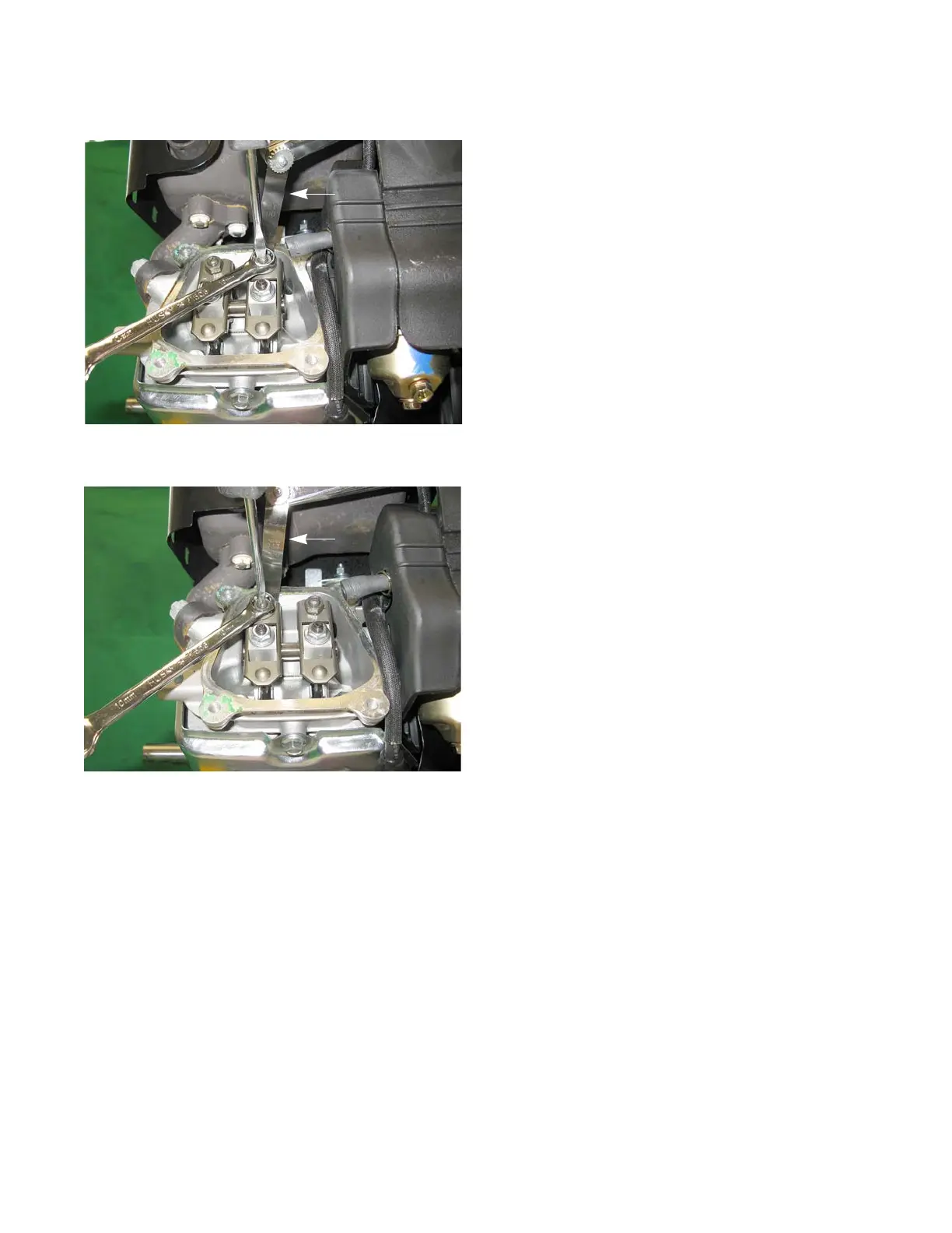
6a. Intake valve lash should be 0.004” - 0.006”
(0.10 - 0.15 mm). See Figure 1.16.
6b. Exhaust valve lash should be 0.006” - 0.008”
(0.15 - 0.20 mm). See Figure 1.17.
6c. Use a 10mm wrench to loosen the jam nut.
Adjust the jack screw using a small flat headed
screw driver.
• Tighten the jack screw to close-up the clearance
between the end of the valve stem and the contact
point on the rocker arm.
• Loosen the jack screw to open-up the clearance
between the end of the valve stem and the contact
point on the rocker arm.
7. Rotate the engine through several compression cycles:
• Observe the movement of the valve gear.
• Return the piston to TDC compression stroke and re-check the valve lash to confirm consistent movement
of the valve gear, including the slight bump to the exhaust valve from the automatic compression release.
8. Clean-up any oil around the valve cover opening, clean the valve cover, replace the valve cover gasket if nec-
essary.
9. Install the valve cover, tightening the valve cover screws to a torque of 62 - 80 in-lbs (7 - 9 Nm).
IMPORTANT: Over tightening the valve cover will cause it to leak.
10. Install the spark plug.
11. Test run the engine before returning it to service.