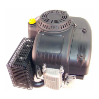
61/65/70/75 Series Horizontal Shaft Engines
56
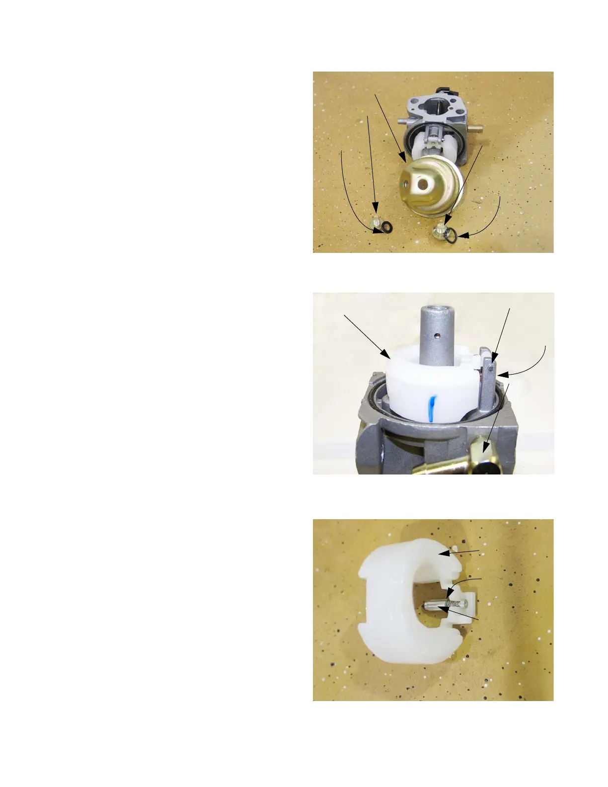
3. Remove the bowl bolt using a 10mm wrench. See
Figure 4.28.
NOTE: From this point an assessment can be made
about the viability of rebuilding the carbure-
tor.
• If extensive corrosion is evident, replace the
carburetor.
• If varnish build-up is too extensive to clean,
replace the carburetor.
4. When inverted, the float should rest in a level posi-
tion. See Figure 4.29.
5. Remove the pin that the float hinges on to remove
the float.
NOTE: The float is not adjustable. Spring tension
against the float valve begins to build from
the horizontal position, putting progressively
more pressure between the tip of the valve
and the seat. See Figure 4.30.
NOTE: Because the float valve is crucial to the func-
tioning of the carburetor, and the viton tip of
the valve is subject to wear, technicians
should replace the valve and spring any time
the carburetor is disassembled for cleaning.
• A square cross-section gasket seals the bowl to
the body of the carburetor.
Figure 4.28
Float bowl
Drain bolt
Flat fiber
gasket
Bowl bolt
with recess in
head for O-ring
Gasket seal
Figure 4.29
Float
Float pin
Float valve
Fuel inlet
Figure 4.30
Float
Compression
spring
Float valve
 Loading...