FUEL SYSTEM AND GOVERNOR
57
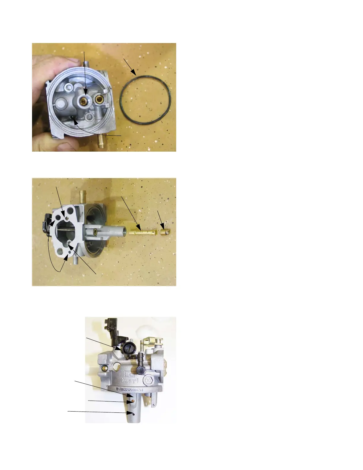
6. Remove the main jet using a narrow-shank straight
blade screwdriver. See Figure 4.31.
NOTE: Fuel enters the central column through a port
about 1/2” (1cm) from the bottom, to help prevent
the ingress of any residue in the bottom of the
bowl.
NOTE: The orifice in the main jet meters fuel into the cen-
tral column.
NOTE: Air from the main jet emulsion port enters the cen-
tral column near the top, then gets bubbled
through the emulsion tube into the metered fuel
flow to promote atomization.
NOTE: The main jet secures the emulsion tube in the cen-
tral column of the carburetor. See Figure 4.32.
7. The throttle stop screw has a large pliable lip around
the head of the screw. That lip secures a metering
plug for the pilot and transition ports. Remove the
screw to reach the plug. See Figure 4.33.
Figure 4.31
Main jet
Bowl gasket
Bowl vent port
Figure 4.32
Bowl vent ports
Emulsion air port: main jet
Emulsion air port: pilot jet
Emulsion tube
Main jet
Figure 4.33
Fuel feed leg
on central
column for pilot
and transition
shot plug in feed bore
Fuel port to
central column
Throttle stop screw