61/65/70/75 Series Horizontal Shaft Engines
78
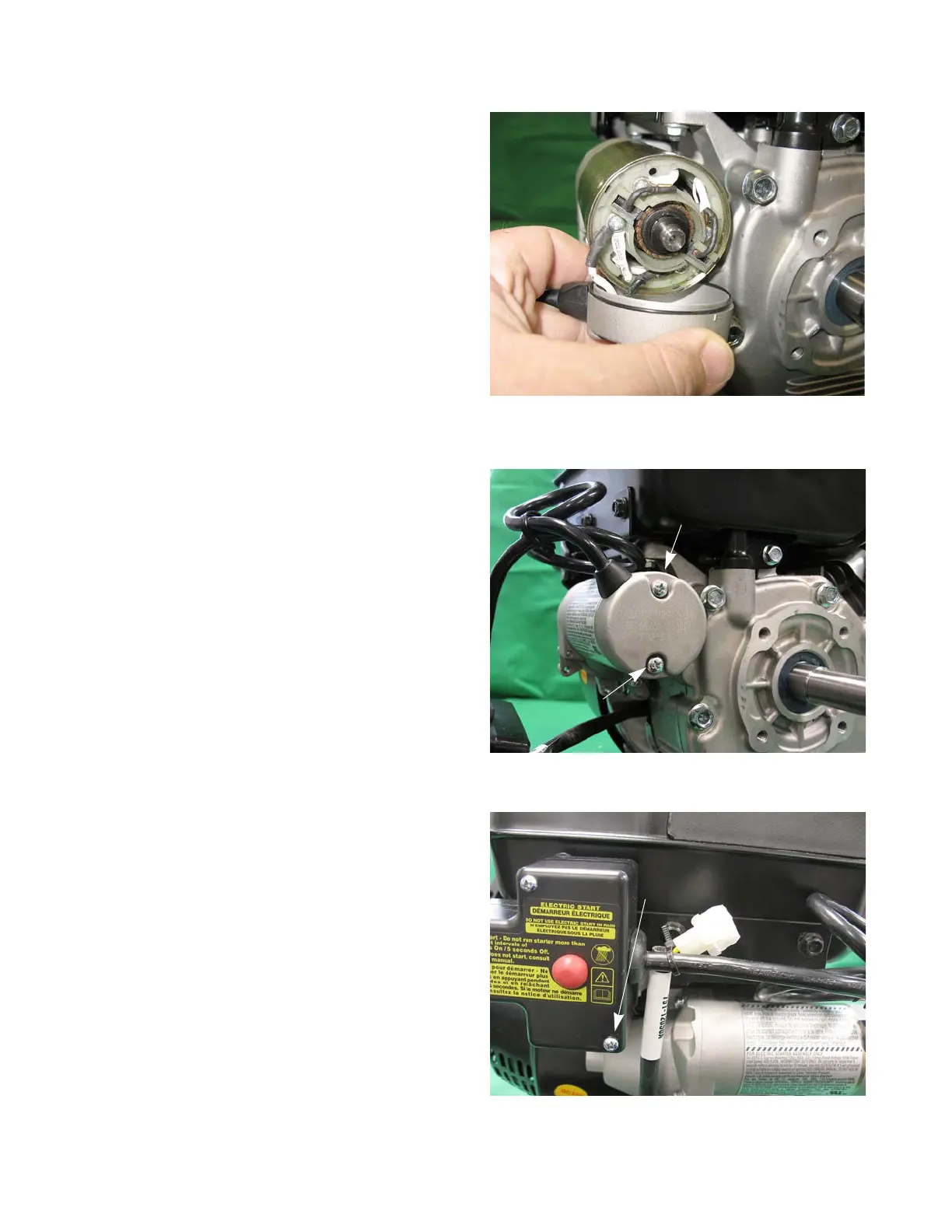
18. Attach the white and black wires of the harness to
the brush housing. See Figure 6.22.
19. Set the end cap in place.
NOTE: The holes should be at the 6 & 12 O’clock
positions.
20. Install the two starter screws with new insulator
washers.
21. Attach the switch box to the engine.
NOTE: The longer screw goes in the bottom hole.
NOTE: The bottom screw must pass through the
hole in the front shroud, then enter the hole
in the mounting bracket.
22. Attach the alternator harness to the starter harness
with a cable tie. See Figure 6.24.
23. Test run the engine in a safe area before returning it
to service.
Figure 6.23
12 O’clock
6 O’clock