Chapter 10: Crankshaft, piston and Connecting Rod
96
10d. Using a seal protector, slide the sump on to
the crank shaft.
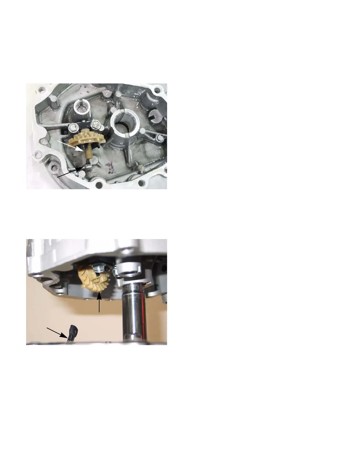
NOTE: The governor arm must slide between
the governor cup and the governor arm stop.
See Figure 10.29.
NOTE: Watch the governor arm as the sump is
slid into place. Rotate the arm as needed to
allow the arm to slip into place.
See Figure 10.30.
10e. Rock sump until it seats fully against the
cylinder block.
10f. Install the sump bolts and tighten to a
torque of 89 in-lbs (10 Nm).
NOTE: Use a star torque pattern to tighten the
sump bolts.
11. Install the cylinder head by following the steps
described in Chapter 9: Cylinder head.
12. Install the muffler by following the steps
described in Chapter 8: Exhaust.
13. Install the fuel tank by following the steps
described in Chapter 4: Fuel systems and Gov-
ernor.
14. Install the carburetor by following the steps
described in Chapter 3: Air Intake and Filters.
15. Install the flywheel and module by following the
steps described in Chapter 7: Ignition system.
NOTE: If equipped, install the engine brake by
following the steps described in the application’s
service manual.
16. Install the blower housing and starter by follow-
ing the steps described in Chapter 6: Starter.
17. Install the engine on the application by following
the steps described in the application’s service
manual.
18. Install the spark plug by following the steps
described in Chapter 7: Ignition system.
19. Fill the engine with oil and fuel by following the
steps described in Chapter 1: Introduction.
20. Test run the engine in a safe area and make any
carburetor and governor adjustments needed.
Figure 10.29
Governor
cup
Governor arm stop
Figure 10.30
Governor arm
Governor
gear
www.mymowerparts.com
For Discount White Outdoor Parts Call 606-678-9623 or 606-561-4983
 Loading...


