Chapter 4: The Fuel System and Governor
43
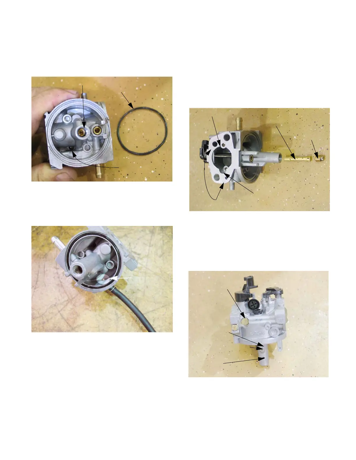
• A square cross-section gasket seals the bowl to
the body of the carburetor.
6. Remove the main jet by using a narrow-shank
straight blade screwdriver. See Figure 4.42.
NOTE: A primer carburetor will have an addi-
tional port so that the air from the primer bulb
can enter the float chamber. See Figure 4.43.
NOTE: Fuel enters the central column through a
port about 1/2” (1cm) from the bottom, to help
prevent the ingress of any residue in the bottom
of the bowl.
NOTE: The orifice in the main jet meters fuel into
the central column.
Figure 4.42
Main jet
Bowl gasket
Bowl vent port
Figure 4.43
Port for the
primer
NOTE: Air from the main jet emulsion port
enters the central column near the top, then gets
bubbled through the emulsion tube into the
metered fuel flow to promote atomization.
NOTE: The main jet secures the emulsion tube
in the central column of the carburetor.
See Figure 4.44.
7. The throttle stop screw has a large pliable lip
around the head of the screw. That lip secures a
metering plug for the pilot and transition ports.
Remove the screw to reach the plug.
See Figure 4.45.
Figure 4.44
Bowl vent ports
Emulsion air port: main jet
Emulsion air port: pilot jet
Emulsion tube
Main jet
Figure 4.45
Welch plug
Fuel feed leg
on central
column for pilot
and transition
shot plug in feed bore
Fuel port to
central column
www.mymowerparts.com
For Discount White Outdoor Parts Call 606-678-9623 or 606-561-4983
 Loading...


