Chapter 7: Ignition System
71
• Resistance figures that are vastly lower may
indicate a short in the windings being tested.
• Resistance figures that are vastly higher (or O.L)
may indicate a fault in the windings being tested.
NOTE: Intermittent failure requires tests for volt-
age and resistance to be made when the engine
is cold, and again when it is hot. Typical cus-
tomer complaint: “It stops after I mow for 10 min-
utes and I can’t get it to re-start”.
• To confirm that the problem is ignition-based, it
is necessary to “catch it in the act”.
• Resistance normally increases slightly as tem-
perature increases.
NOTE: Failure of the magnets in the flywheel is
exceedingly rare. To test the magnets, simply
hold an item made of ferrous metal roughly 1/4”
(.635cm) away from the magnets in the flywheel.
It should be drawn to the flywheel. A wrench or
screwdriver is suitable for this test.
NOTE: An inexpensive compass or bar magnet
can be used to confirm opposite polarity of the
flywheel magnets. See Figure 7.13.
Figure 7.13
Opposite poles of bar magnets
are attracted to opposite pole
flywheel magnets for the sake
of illustration
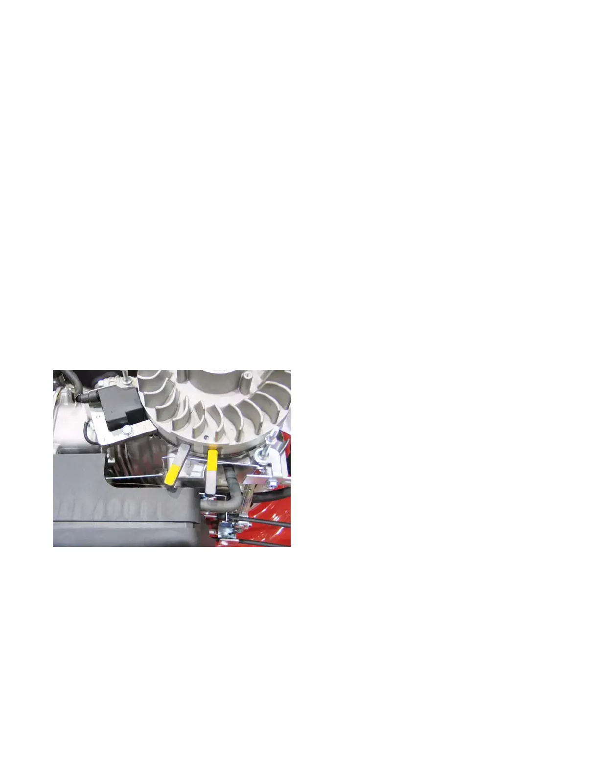
5. Inspect the flywheel.
The flywheel is a frequently forgotten component of the
ignition system. It holds the magnets that induce a field
in the module which in turn produces a spark. But it
also controls the timing of the ignition system by con-
trolling when the magnets are introduced to the mod-
ule.
A sheared flywheel key will throw off the ignition timing.
To inspect the flywheel and key:
1. Remove the recoil assembly by following the
steps describe in Chapter 6: Starter.
2. Remove the flywheel by following the steps
described in the flywheel section of this chapter.
3. Inspect the flywheel key and the key way on the
crank shaft.
NOTE: If the flywheel key is damaged, replace
it. If the keyway on the crankshaft is damaged,
the engine must be short blocked.
www.mymowerparts.com
For Discount White Outdoor Parts Call 606-678-9623 or 606-561-4983
 Loading...


