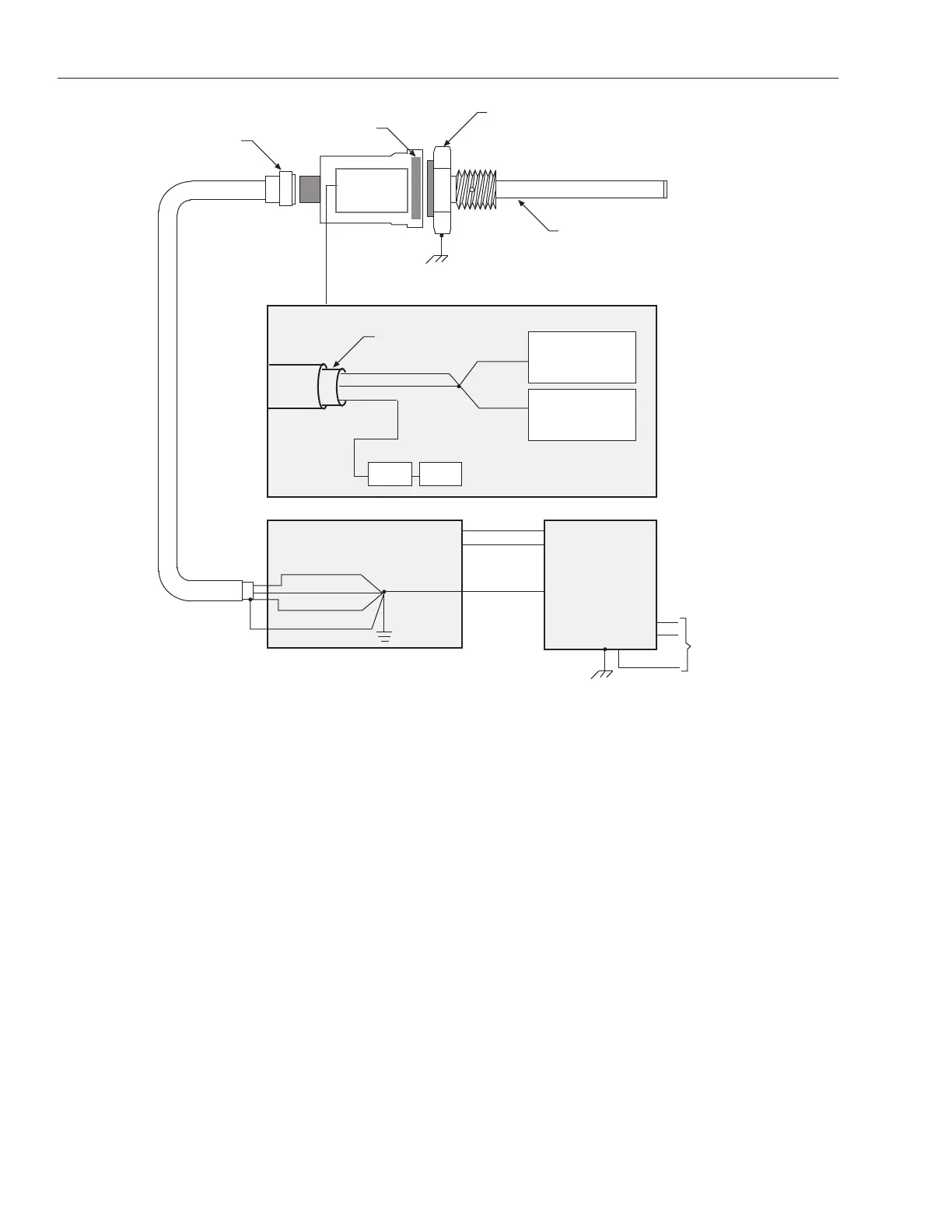
EasyManuals Logo

MTS Systems Temposonics II LDT User Manual

Default Icon
65 pages
To Next Page IconTo Next Page
To Previous Page IconTo Previous Page
Page #15 background imageLoading...
Page #15 background image
12
3. Grounding
Figure 3-1
Grounding
Signals Return(s)
Power Return
Frame
Bracket Cover
Cable Shield (no connection)
Head Assembly Grounding Diagram
Signals Return(s)
Power Return
Frame
+Vcc
-Vee
Control Module
(AOM, DIB, Counter Card or other)
(internal to
head enclosure)
Connector
(10 pins)
Ground connection between bracket
and outer cover made by threads
Transducer Rod
(3/8 in. stainless steel)
Machine Ground
Flange
(electrically isolated from threads)
Power Return
Shield Ground
(non current carrying)
AC Line
Bracket
Power Supply
Driver/Amplifier
Module
Option Module

Other manuals for MTS Systems Temposonics II LDT

Questions and Answers:

Question and Answer IconNeed help?

Do you have a question about the MTS Systems Temposonics II LDT and is the answer not in the manual?

MTS Systems Temposonics II LDT Specifications

General IconGeneral
BrandMTS Systems
ModelTemposonics II LDT
CategoryTransducer
LanguageEnglish