6
4. Move the permanent magnet full-scale to check that it moves freely. If not (if the magnet rubs on the transduc-
er) you can correct this by mounting a support bracket to the end of the transducer. Long transducers may
need additional supports to be attached to the transducer rod. Transducer supports are described later in this
section.
2.1 Types of Transducer Supports
Long transducers (48 inches or longer) may require supports to maintain proper alignment between the
transducer rod and the permanent magnet. When transducer rod supports are used, special, open-ended
permanent magnets are required.
Transducer supports attached to the active stroke length must be made of a non-ferrous material, thin
enough to permit the permanent magnet to pass without obstruction. Because the permanent magnet
does not enter the dead zone, supports connected within the dead zone may be made of any material.
The main types of supports are loop, channel, and guide pipe supports.
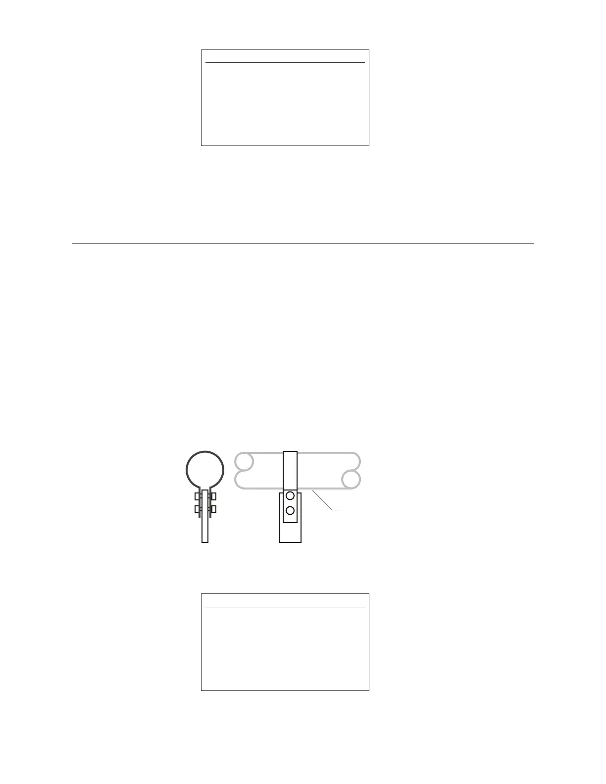
2.1.1 Loop Supports
Loop supports are fabricated from non-ferrous materials, thin enough to permit free movement of
the magnet. Loop supports are recommended for straight transducers. They may be used alone or
with channel supports. Figure 2-4 illustrates the fabrication of a loop support.
Figure 2-4
Loop Support
NOTE:
When open magnets are used, ensure the
transducer rod remains within the inside
diameter of the magnet throughout the
length of the stroke. If the transducer rod
is allowed to enter the cut out area of an
open magnet, the transducer signal
could attenuate or be lost. See Figure 2-7.
NOTE:
Clearance between the magnet and the
transducer rod is not critical. However,
contact between the components will
cause wear over time. The installation of
supports or readjustment of the supports
is recommended if the magnet contacts
the transducer rod.
 Loading...