25
6.3.1 Latch Pulse
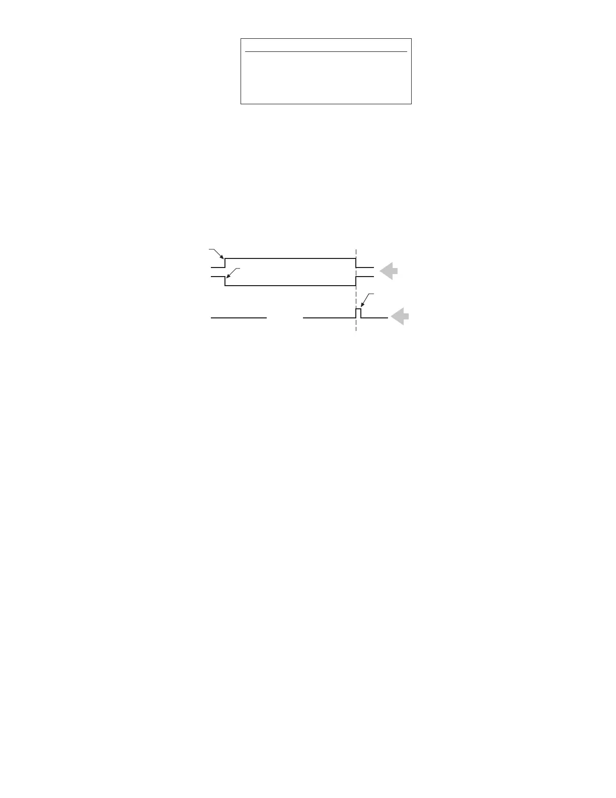
The latch pulse is a nominal 1µs wide pulse that is used as a “data valid” signal. Data is invalid
when the signal is high. Data is valid and can be read when the signal is low. The standard latch
pulse can be “gated” with a read type pulse generated at the receiver device. The user performs
the gating logic external of the counter card. The latch pulse is available on pin 3 of the digital
counter card. (An optional 12µs wide latch pulse is available if the 1µs pulse is too fast.)
Figure 6-2
Latch Pulse
6.3.2 Protocol
The recommended protocol for assuring that valid count data is received from the counter card is
as follows:
• Poll the data-valid output for a logic 1, indicating that data is currently invalid, but will soon be
valid.
• Poll the same output for a logic 0, indicating that new, valid count data is present at the out-
puts of the counter card.
• Bring the latch-inhibit input of the counter card low. This prevents the outputs of the counter
card from changing.
• When ready, accept the data into the user control system processing
• After sampling, bring the latch-inhibit input high.
If this protocol is followed, data presented to the user control system from the input module will
be valid count data, and the effects of electrical noise and signal transitions will be minimized.
6.3.3 Latch Inhibit Input
The latch inhibit input is available on the digital counter card to “freeze” the binary output signal.
The users’ receiver provides an inhibit signal to pin 24 on the counter card. The signal must be a
low TTL level to inhibit downloading of the updated displacement information into the output
registers; the receiver is then provided unchanging data.
Connect complementary gates from the
Digital Interface Box (DIB)
or Digital Personality Module (DPM) to
Digital Counter Card -- Pins 4 and 5
Latch Pulse
+ Gate
- Gate
Pin 3 of Digital Counter Card
Data VALID
Date INVALID
(during Latch Pulse)
TTL Level
TTL Level
 Loading...