8
2.2 Open Magnets
When using an open magnet, make sure the rod is positioned at all times within the “active” zone of the
magnet. The transducer cannot operate properly unless the entire stroke of the transducer rod is located
within this zone. The active zone, as shown in Figure 2-7, lies within the inside diameter of the magnet.
Figure 2-7
Active Zone for Open Magnets
2.3 Spring Loading or Tensioning
The transducer rod (flexible or rigid) can be spring loaded or tensioned using a stationary weight. Attach
a spring mechanism or weight to the dead zone of the transducer rod with a clamping device which will
not deform the transducer rod. The maximum weight or spring tension is 5 to 7 lbs.
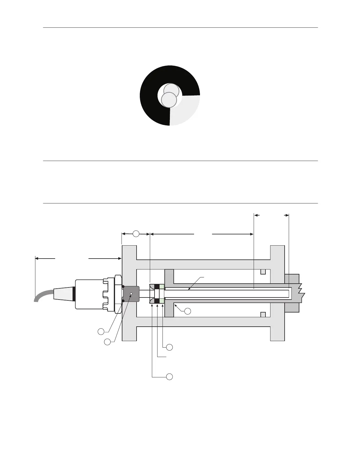
2.4 Cylinder Installation
Figure 2-8
Typical Cylinder Installation
Null (as specified)
Minimum: 2 in. (50mm)
NON-ferrous Spacer, Part No.: 400633
Magnet, Type SR-12
Part No.: 201542
(1.29 in. (32.76 mm) O.D.
(other options available)
Chamfered Rod Bushing
1
5
Nylok® Insert
6
2
O-ring (MS 28778-8 or equivalent)
Part No.: 560315
Piston Head and Rod Assembly
4
0.5 in (12.7 mm) Bore
Active Stroke3
Minimum: 5 in. (127 mm)
Dead Zone:
2.50 in. (63.5 mm)
for stroke lengths
up to 179.9 in;
3 in. (76.2 mm)
for stroke lengths
≥180 in.
 Loading...