18
4.4 Digital Counter Card
The digital counter card measures the on-time of the DPM pulse duration signal. This is accomplished by
using a crystal oscillator with frequency selected to provide the desired resolution (counts per inch). A 27-
28 MHz crystal is typically used.
The leading edge of the pulse duration signal enables the counter registers, and the trailing edge triggers
a “latch pulse” to download the count into the output registers. The latch pulse is normally available for
the receiver device to interpret as a “data valid” signal: normally low = data valid, TTL level high = data
invalid. The latch pulse frequency is the same as the interrogation frequency, and the duration is nominal-
ly 1 microsecond.
Scaling of the counter card is accomplished by matching the counter card crystal frequency to the gradi-
ent of the transducer to provide 0.001 inch, 0.0005 inch, etc. per count. Unscaled systems may require
scaling within the receiver device, depending upon desired accuracy.
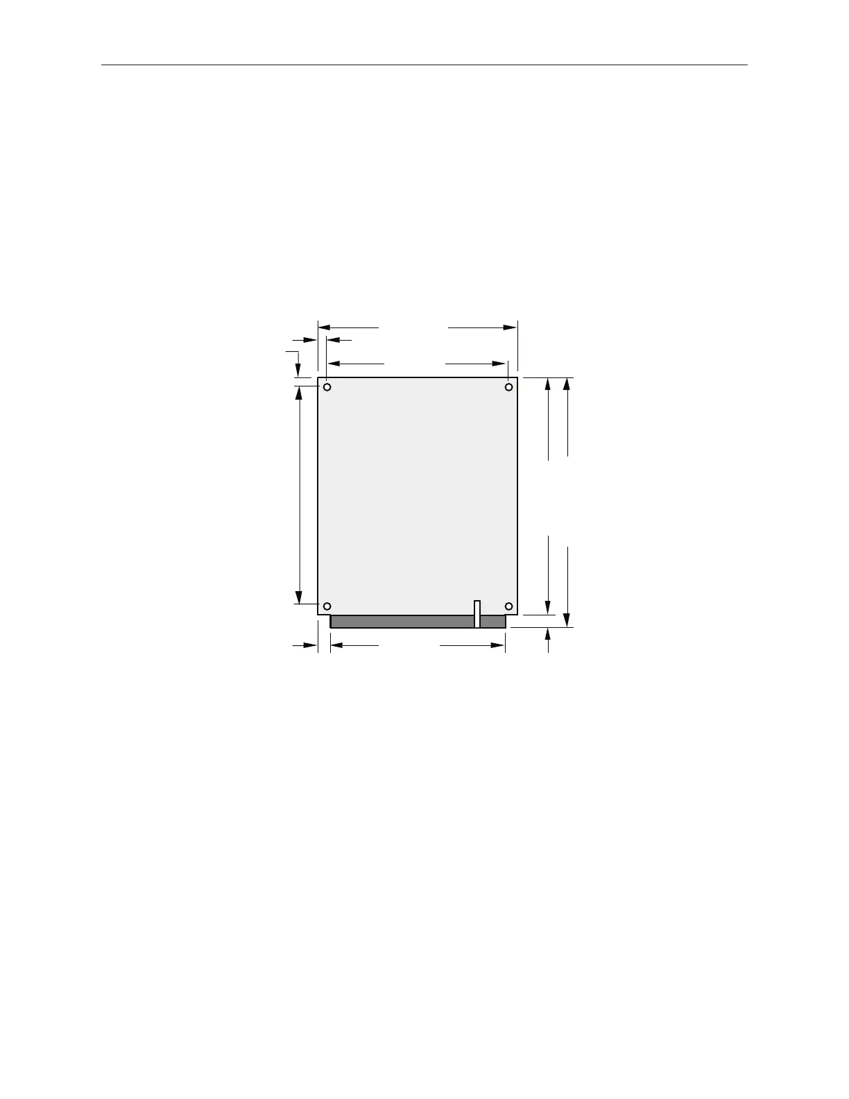
Figure 4-8
TCS Digital Counter Card
 Loading...