45
APPENDIX B DPM Programming Procedure (Asynchronous Mode)
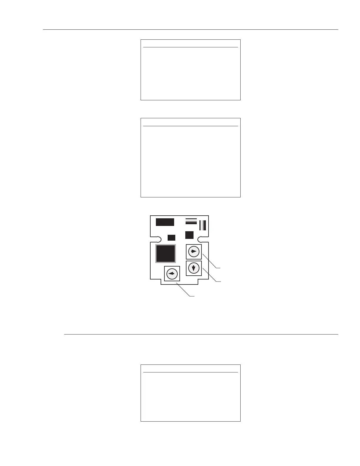
Figure B-1
DPM Switch Locations
B.1 Setting Number of Recirculations
SW1 and SW2 are programming switches that are used to set the number of recirculations (1 through
127). Refer to Table 2B (next page).
NOTE:
The number of recirculations are speci-
fied by the customer at time of order.
This number is based on resolution and
frequency. You can use Table 1B to
choose the number of recirculations
based on resolution using a 27 - 28 MHz
crystal.
WARNING!
The DPM is a static sensitive device and
should be treated as such. MTS recom-
mends that a static wrist strop be worn
during installation and programming.
Also, these procedures are to be conduct-
ed in a clean (dust and moisture-free)
environment.
A small flat head screwdriver should be
used to program the switches. See Figure
B-1 for switch locations.
NOTE:
DPM programming switches are pre-set
at the factory. Only authorized OEMs are
permitted to program this device. Call
MTS before making any adjustments to
the switches.
REMOVING THE TRANSDUCER COVER
VOIDS THE WARRANTY.
 Loading...