13
4. Digital System Configurations
The typical digital system configurations are shown in Figures 4-1, 4-2, and 4-3. Figure 4-1 is a “full” digital sys-
tem. A full digital system includes a Temposonics II LDT with an integrated Digital Personality Module (DPM) and
a Digital Counter Card and supplies either a Binary Coded Decimal (BCD) or Natural Binary output. When
ordered as a scaled system, the components are matched and factory calibrated and will provide an exact, discrete
resolution.
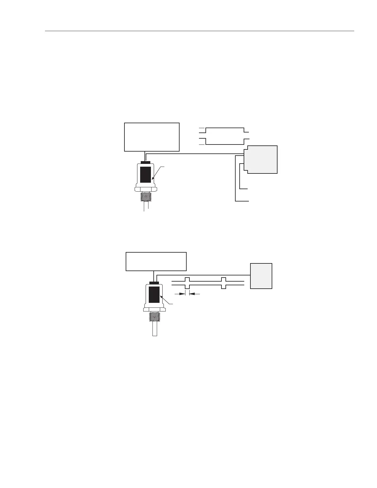
Figures 4-2 and 4-3 illustrate other system configurations which use the output from either the Digital Personality
Module (DPM) or the RS422 Personality Module (RPM) as direct input into a control system. The DPM provides a
pulse duration output and the RPM provides an RS422 interface.
Figure 4-1
Digital System Configuration with DPM, LDT and Digital Counter Card
Figure 4-2
Temposonics II Digital System Configuration
with RS422 Personality Module
Belden YR8105 or equivalent (5 pair)
Power Supply Requirements
• ±12 to ±15Vdc @ 140mA (bipolar)
RS422 Personality Module
User's
Control
System
1µs
RPM
Belden YR8105 or equivalent (5 pair)
Power Supply Requirements
• ±12 to ±15Vdc
@ 150mA (bipolar)
• + 5Vdc
@ 1.2A req. for Counter Card
Digital Personality Module
0
Pulse Duration Output
0
TTL Level
Natural Binary or BCD Output
+5Vdc
Digital
Counter
Card
TTL Level
DPM
 Loading...