21
6. Electronic Connections
6.1 General
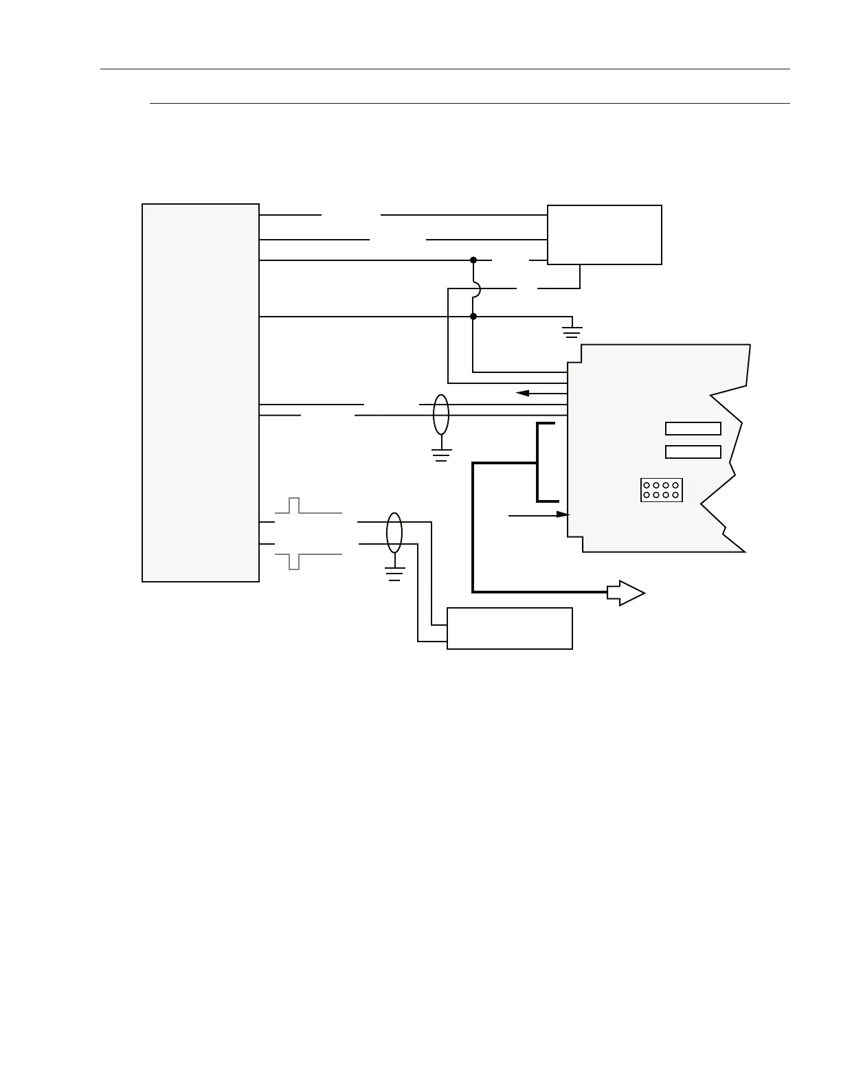
Figure 6-1 (below) illustrates the interconnections of a typical digital system comprised of a Temposonics
II transducer, an integrated Digital Personality Module (DPM) and a Digital Counter Card.
NOTES:
1. It is common practice to apply earth ground to power supply common terminals near power supply. Refer to Section 3 for grounding dia-
gram.
2. Jumpers W20 and W22 make Pin 24 inhibit and Pin 3 Latch Pulse
Jumpers W21 and W23 make Pin 24 Latch Pulse and Pin 3 inhibit.
Figure 6-1
Typical Digital System Connections
 Loading...