5
1. Use the 3/4 inch (19 mm), 16 UNF thread of the transducer to mount it at the selected location. Leave room to
access the hex head. If a pressure or moisture seal is required, install an O-ring (type MS 28778-8 is recom-
mended) in the special groove. Use the hex head to tighten the transducer assembly.
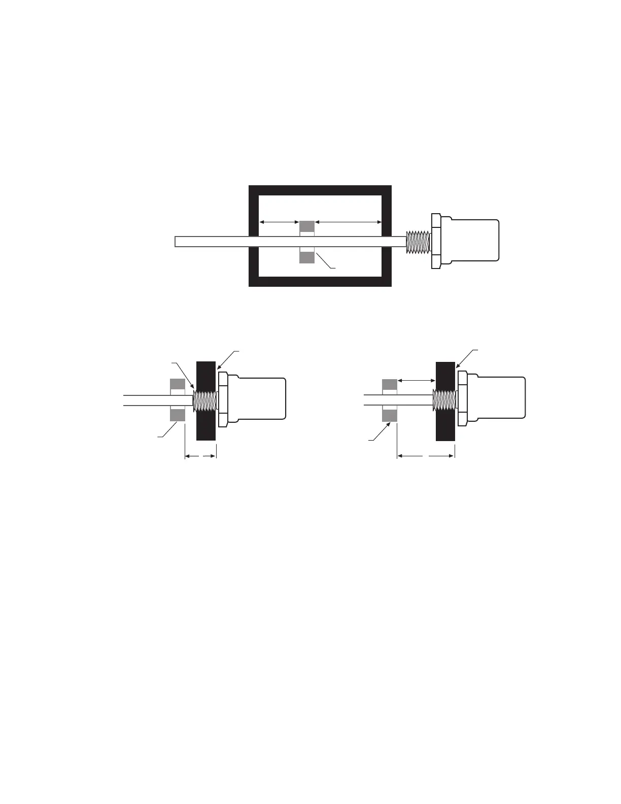
2. Install the permanent magnet over the LDT rod. Mount the permanent magnet to the movable device whose
displacement will be measured. To minimize the effect of magnetic materials (i.e. iron, steel, etc.) on the mag-
netic field of the permanent magnet, ensure the minimum spacing requirements are met as shown in Figure 2-
4. (Any non-magnetic materials can be in direct contact with the permanent magnet without affecting perfor-
mance.)
Figure 2-3a
Minimum Magnet Clearance Using Magnetic Supports
Figure 2-3b Figure 2-3c
Minimum Null Space Using Non-Magnetic Support Minimum Null Space Using Magnetic Support
Notes:
1. The magnet must not contact ferromagnetic materials (such as iron or steel). Clearances are required between the surface of the magnet
and ferromagnetic material, as shown. Non-ferrous material (such as copper, brass, or 300 series stainless steel) may contact the magnet
without affecting transducer performance.
2. Standard Null Space is 2 inches. There is no maximum limit for Null Space. Less then 2 inches can be specified if magnet clearances meet
requirements illustrated above.
 Loading...