33
3. Resetting the Counter Card with DIP Switches
For this procedure, the receiver device must be capable of reading each of the Counter Card out-
put bits. For example, the System CRT or LED display may be connected to each bit connection
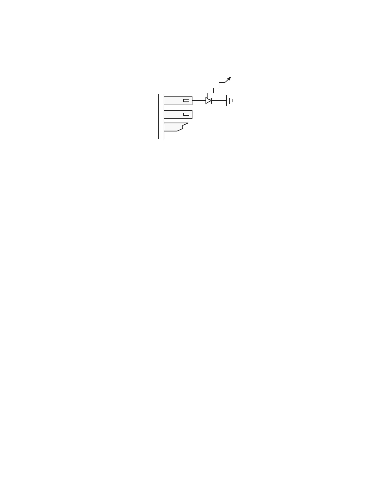
on the input module. If this is not possible, a string of LEDs must be connected to the counter
card connector to read each active bit (Refer to Figure 7-1 for a typical connection). Figures 6-5
and 6-6 show DIP switches S1 and S2, along with tables for determining the switch settings.
Figure 6-3
Testing Counter Card Output
a. Binary Output
Take the following steps (Refer to Figure 6-4, next page):
1. Before changing any DIP switch positions, record the factory-set positions for reference.
2. Move the magnet to the desired null position. Clamp it in place to prevent movement.
3. Reset all switch segments to the LO (closed) position, taking note of alignment marks on the
board.
4. If a PLC or readout device indicates the equivalent counts, write this value in row A of the dia-
gram in Figure 6-4. Then convert this number to binary and write it in row B. To ensure that
the count is correct, move the magnet through its stroke and observe the count change. For
example, a 24 inch stroke unit with 0.001 resolution should yield a 24,000 count change.
Alternatively, read each active bit on the counter card output and record into row B of the dia-
gram.
5. Determine the complement of the binary number in row B, by changing 1s to 0s and 0s to 1s.
Write this complement in row C.
6. Use the number from row C to mark the columns E and F. If the corresponding bit from C is 1,
mark and X in column F (open or HI). If the corresponding bit is 0, mark an X in column E
(closed or LO).
7. Turn off power, then set each switch segment to the value (HI or LO) indicated by the Xs in
columns E and F.
8. Apply power to the system and check that the output is now zero.
 Loading...