50
C.3 Changing Polarity of Interrogation Signal
This procedure is used when connecting a negative pulse transducer to a positive pulse DIB, or when
connecting a positive pulse transducer to a negative pulse DIB.
1. Remove the 4 cover screws on the DIB.
2. Remove cover with PCB connected. Turn component side up with J1 to the left and J2 to the right as
you face the board.
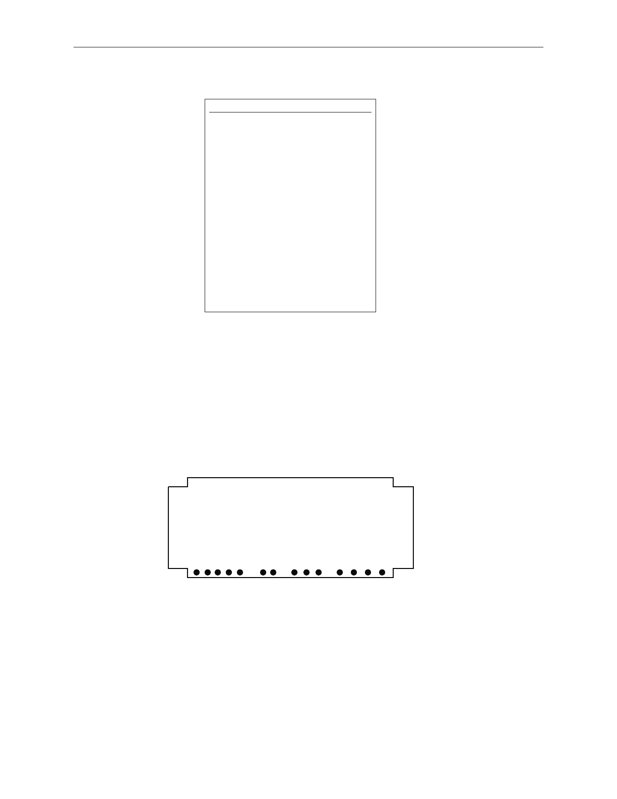
3. Make one connection to Pin-E on the J2, 6-pin connector, which represents the positive (+) or negative
(-) pulse.
Example:
• Post E14 to J2 Pin-E is (+) polarity
• Post E13 to J2 Pin-E is ( -) polarity
Figure C-1
Digital Interface Box - Posts E1 - E14
NOTE:
The only transducers with a negative
interrogation pulse are original
Temposonics I transducers with stroke
lengths of 12 inches or less (the serial
number indicated on the transducer
label ends with “N” to denote a negative
interrogation pulse).
Temposonics II transducers can pro-
vide either a positive or a negative
interrogation pulse. The positive pulse
is available on Pin 9 of the transducer
connector (white/gray stripe or yellow
wire of pigtail connection). The negative
interrogation pulse is available on Pin
10 of the transducer connector
(gray/white stripe or green wire of pig-
tail connection).
 Loading...