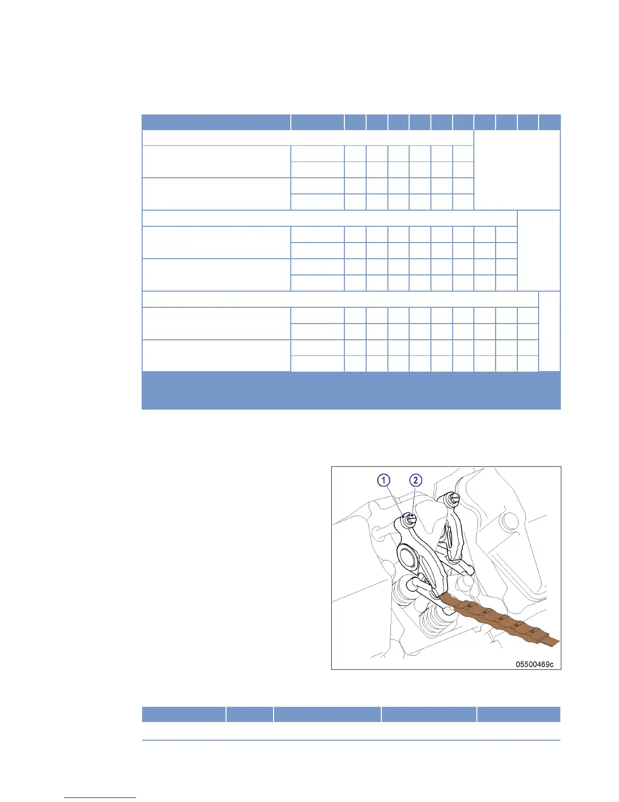
3. Check clearance of all valves at two crankshaft positions (firing TDC and overlap TDC at cylinder A1) in ac-
cordance with the table:
Position Cylinder 1 2 3 4 5 6 7 8 9 10
12V
Firing TDC at cylinder A1 Side A I X I – – X I – – X – –
Side B – X I X I – – X – – I –
Overlap TDC at cylinder A1 Side A – – – X I – – X I – I X
Side B I – – – – X I – I X – X
16V
Firing TDC at cylinder A1 Side A I X – X – X I – – X I – – – – –
Side B I – – X – – I – I X I – I X – X
Overlap TDC at cylinder A1 Side A – – I – I – – X I – – X I X I X
Side B – X I – I X – X – – – X – – I –
18V
Firing TDC at cylinder A1 Side A I X I – I X I – – X I – – X – – – –
Side B – X – X – – – X – – I X I – I X I –
Overlap TDC at cylinder A1 Side A – – – X – – – X I – – X I – I X I X
Side B I – I – I X I – I X – – – X – – – X
I
Inlet: Inlet valve adjustment admissible
X
Exhaust: Exhaust valve adjustment admissible
–
Valve adjustment not admissible
Table 2: Valve clearance settings
4. Use feeler gage to determine the distance between valve bridge and rocker arm.
5. Adjust valve clearance if the deviation from the desired value exceeds 0.1 mm.
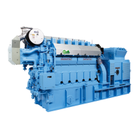
Adjusting valve clearance
1. Loosen locknut (1) and unscrew adjusting
screw (2) by a few threads.
2. Insert feeler gage between valve bridge and
rocker arm.
3. Readjust adjusting screw (2) so that the feel-
er gage just passes through the gap.
4. Tighten locknut (1) to specified torque using a torque wrench while holding adjusting screw (2) firmly with a
screwdriver.
Name Size Type Lubricant Value/Standard
Locknut M12 x 1 Tightening torque (Engine oil) 50 Nm
MS15018/03E 2016-02 | Valve Drive | 81
TIM-ID: 0000000018 - 006