7 Task Description
7.1 Valve Drive
7.1.1 Valve clearance – Check and adjustment
Preconditions
☑ Engine is stopped and starting disabled.
☑ Engine coolant temperature is max. 40 °C.
☑ Valves are closed.
Special tools, Material, Spare parts
Designation / Use Part No. Qty.
Feeler gauge
Y20010128 1
Torque wrench, 20-100 Nm
F30026582 1
Box wrench, 14 mm
F30028346 1
Allen key, 5 mm
F30002815 1
Barring device
F6790714 1
Preparatory steps
1. Remove cylinder head cover (→ Page 39).
2. Remove cover on the bottom of flywheel housing, A side.
3. Install barring device at opening.
4. Rotate crankshaft with barring device in engine direction of rotation until "OT-A1" mark and pointer are
aligned.
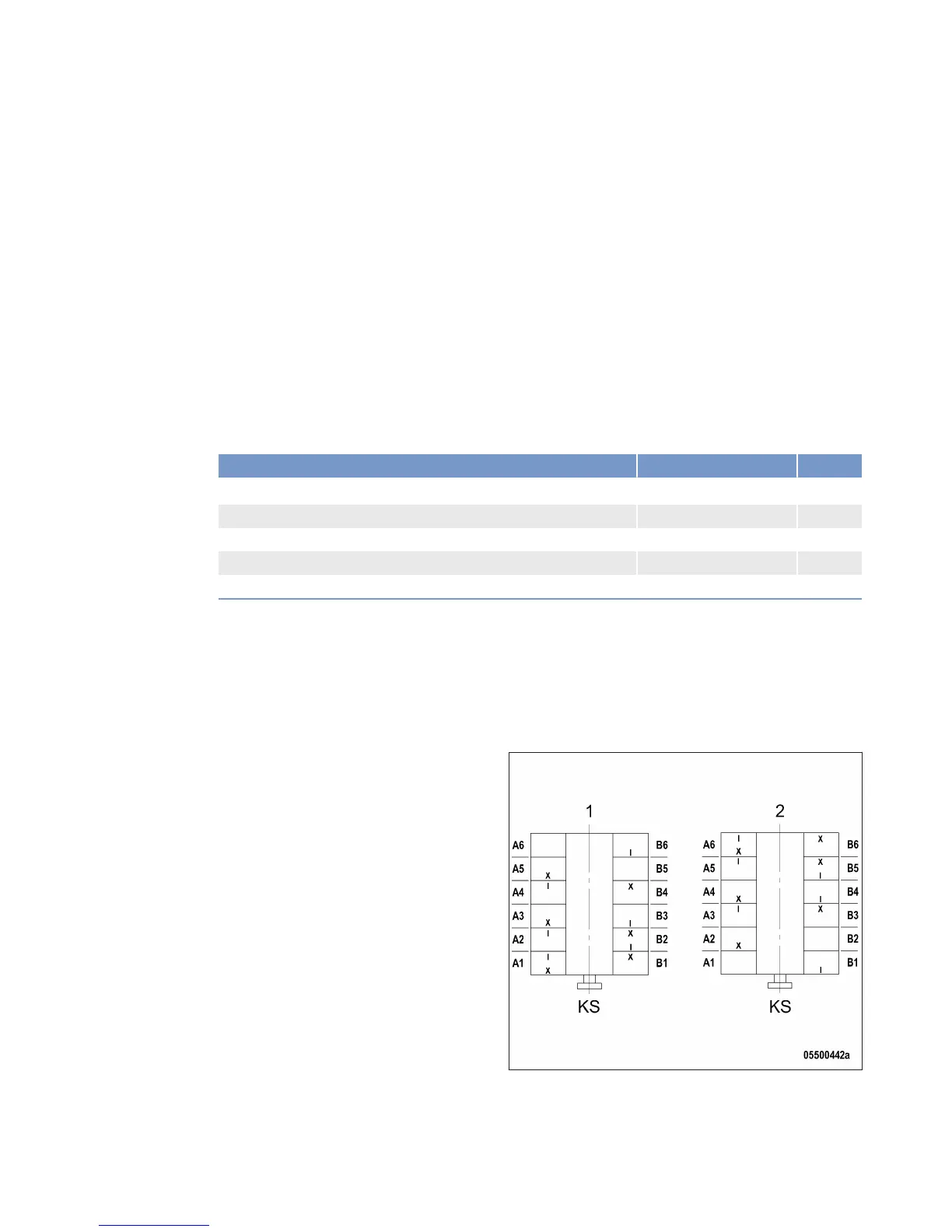
Diagram for 12V engines (two
crankshaft positions)
1 Cylinder A1 is in firing TDC
2 Cylinder A1 is in overlap TDC
I Inlet valve
X Exhaust valve
MS15025/00E 2011-12 | Task Description | 37
TIM-ID: 0000035352 - 001