Industrial remote access router - RSA-series User Guide – Hardware Details and Installation
Page 11
Connectors
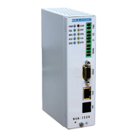
The operating power of the RSA series is supplied at pins 1 and 2 of the PWR
screw terminal connector. The voltage range depends on the model and is
indicated by the “Vr suffix”:
Vr1: 11-36 Vdc, 11-28 Vac
Vr2: 18-60 Vdc, 18-28 Vac
Vr3: 18-72 Vdc, (no ac)
Note: The power input of the unit is not polarised.
You can connect DC power (+/- or -/+) in either way.
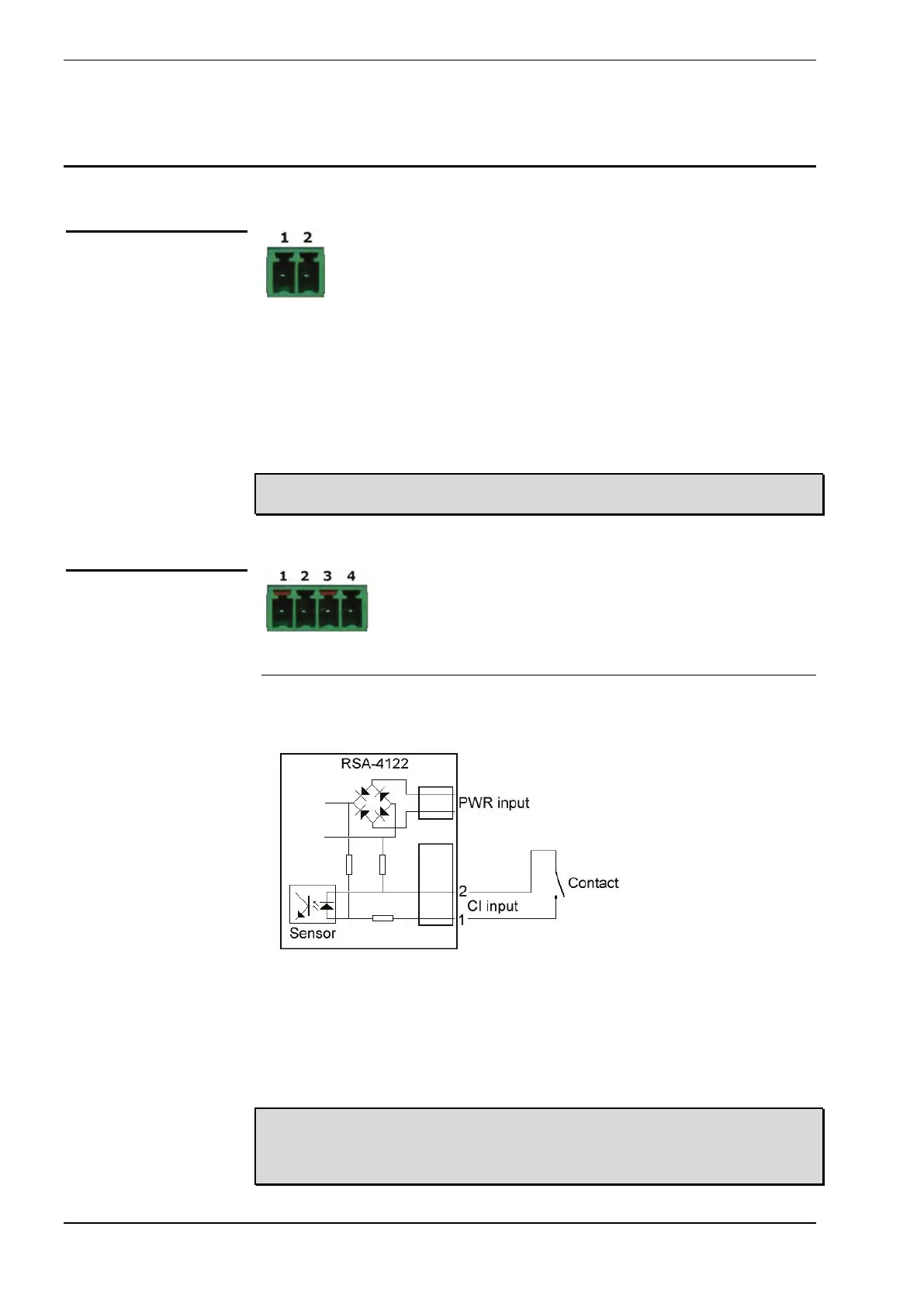
Input
Pins 1 and 2 (marked CI) of the I/O connector are connected to a dry contact
sensor.
Status changes of this input can be monitored via one of the management
services or reported via one of the system alerts:
Email, SNMP-trap, SMS, or read by means of an SNMP-Get.
• Maximum closed contact current (depending on PWR voltage): 6 mA.
• Maximum loop resistance (contact plus cable): 100Ω.
Note: Only use this input for “dry contacts” like the contact of a switch or relay.
Caution: Do not connect to any power source, including the unit’s power
source, nor apply any voltage to the input pins. The contact inputs are
galvanically connected with the unit’s power input.
Power connector
I/O connector
 Loading...