User Guide – Hardware Details and Installation Industrial remote access router - RSA-series
Page 14
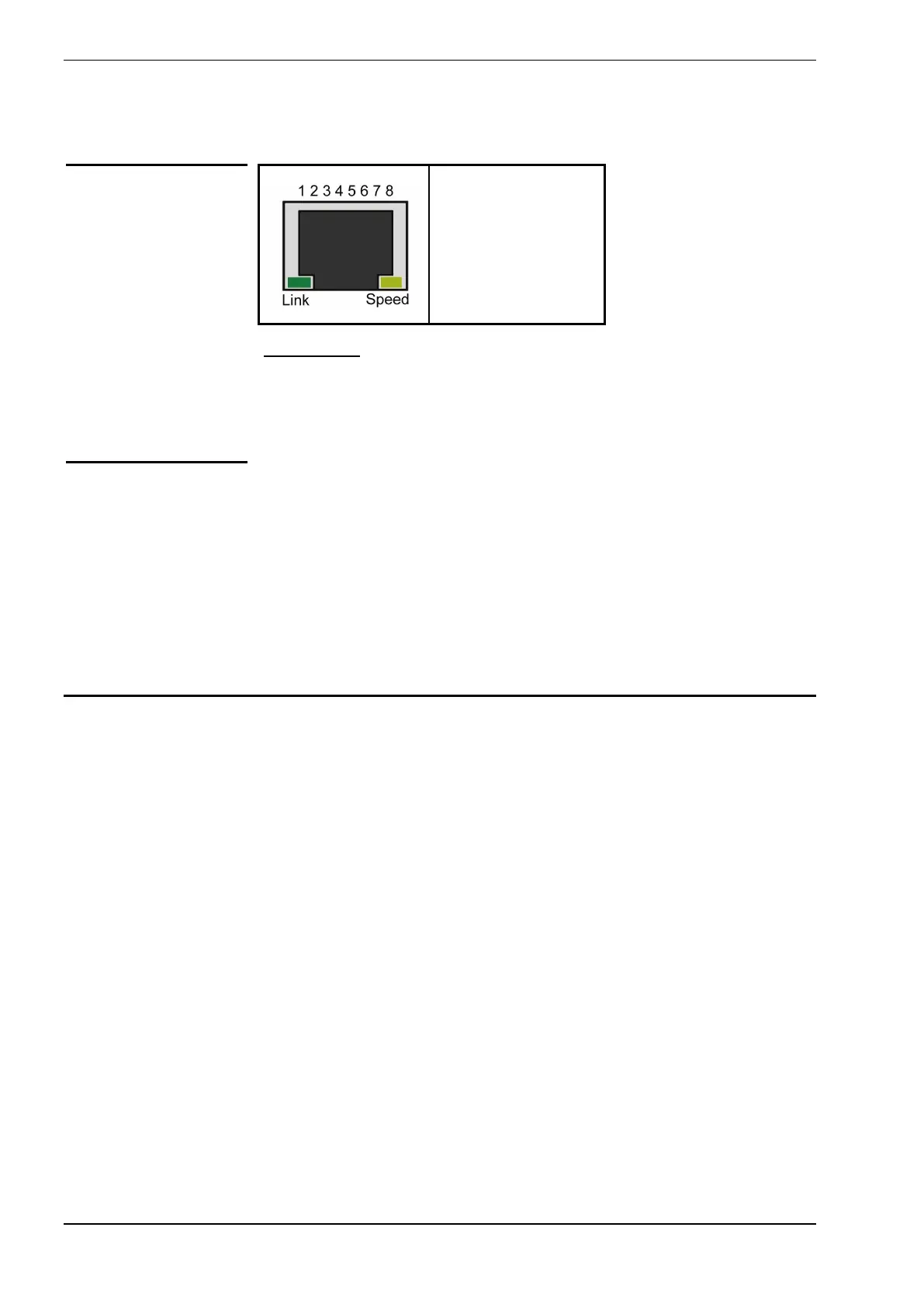
1 = Tx+
2 = Tx-
3 = Rx+
4 = Not connected
5 = Not connected
6 = Rx-
7 = Not connected
8 = Not connected
Ethernet LEDs
• Link (green): Indicates that an Ethernet device is connected with this port.
This LED will blink when there is data activity on this Ethernet port.
• Speed (yellow): Indicates that the Ethernet link is running at 100mbit/s.
The antenna connector (W3/W4-versions only) is of the type “SMA”.
You can connect an antenna with SMA connector directly or use
coaxial cable to an external antenna.
The used antenna and coaxial cable must have a characteristic impedance of
50Ω and must be matched for 900MHz/1800MHz/2100Mhz or
850Mhz/1900Mhz, depending on the frequency bands used by the cellular
network operator.
SIM Card slot (W3/W4-versions only)
The SIM card tray is located at the rear of the unit and can be removed by
pressing the eject button adjacent to the card tray.
Ethernet
Connectors
Antenna Connector
 Loading...