User Guide – Hardware Details and Installation Industrial remote access router - RSA-series
Page 12
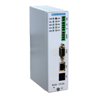
Output
Pins 3 and 4 (marked CO) of the I/O connector are connected to an internal
relay contact (electronic solid state relay). The relay contacts are galvanically
isolated from the device and power input.
The contact state (open/closed) can be controlled by means of an SNMP set,
http request or selected as system alert output.
• Maximum load voltage: 100V
• Maximum load current: 150mA
• Maximum On-resistance: 8Ω.
• Isolation Voltage: 1500 Vrms.
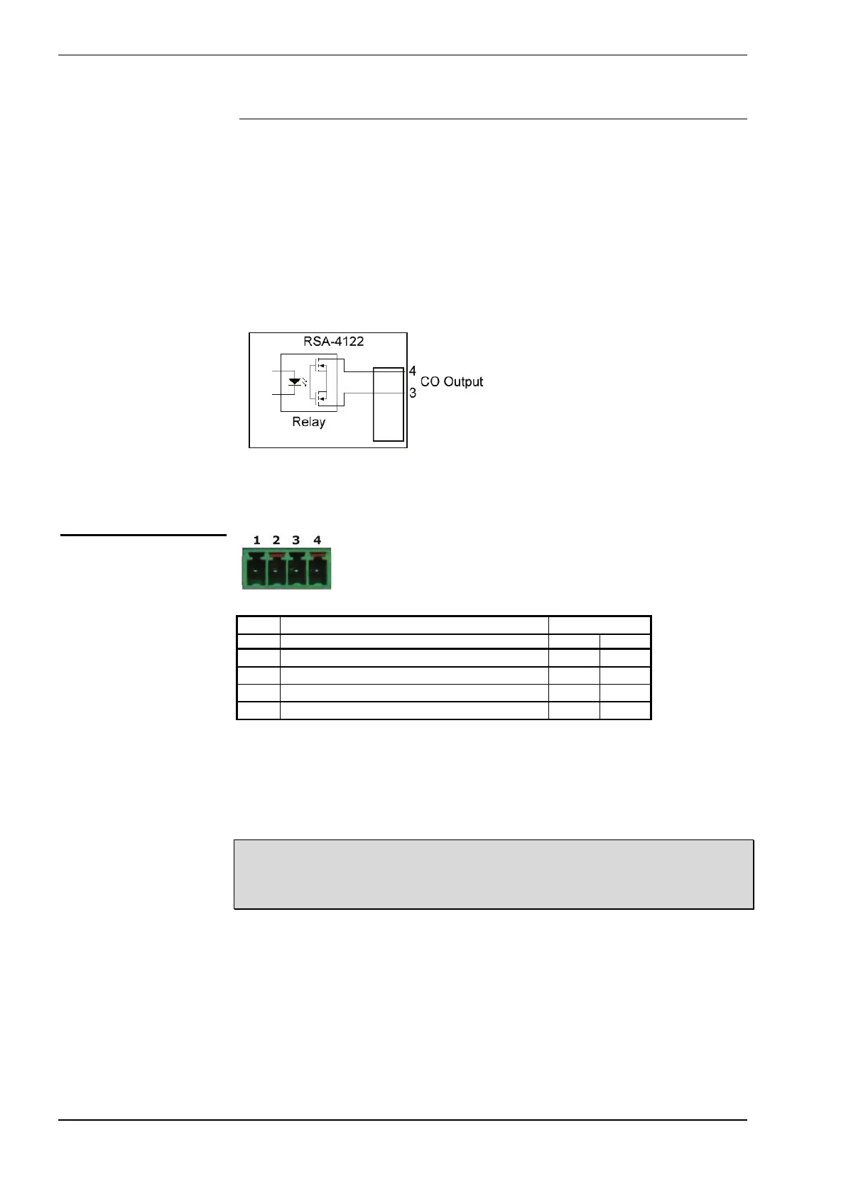
• A 2-wire RS-485 connection is made to pins 2 and 3.
• Pins 1 and 4 are RS-485/RS-422 “Rx” inputs used in 4-wire RS-
485/RS-422 mode. (Note 2).
• Pins 2 and 3 are used for 2-wire RS-485 or as “Tx” outputs in 4-wire
RS-485/R422 mode. (Note 2).
Note 1: The RS-485 output/inputs are not terminated. In general no termination
resistors are needed.
Note 2: The receive data input connector pins 1 and 4 are biased with 10kΩ.
When not used (2-wire RS-485 mode) these pins can remain unconnected.
RS-485 connector
Rx– Receive data input, negative
TR– Transmit/Receive data, negative
TR+ Transmit/Receive data, positive
Rx+ Receive data input, positive
 Loading...