Industrial remote access router - RSA-series User Guide – Hardware Details and Installation
Page 13
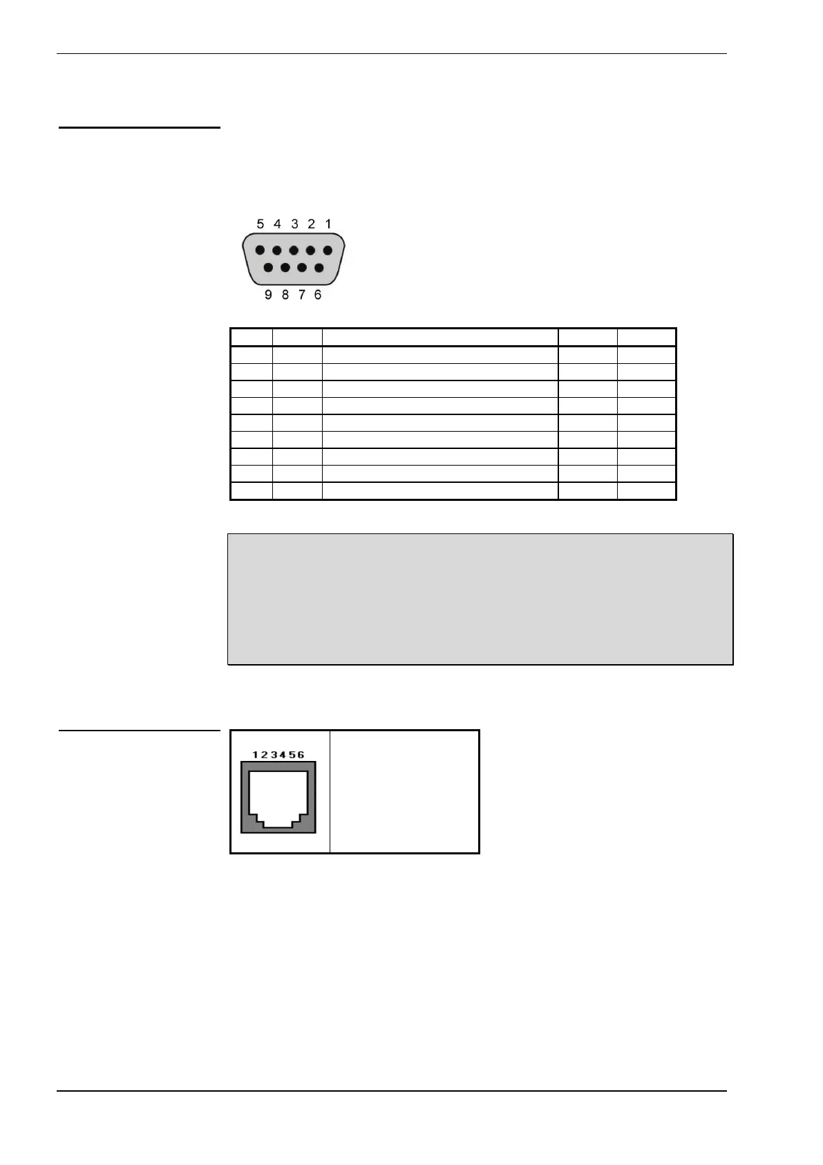
The RS-232 connector is of the type DCE (as used on a modem). It can
connect directly to a DTE type of serial port (as used on a PC) using a straight
cable. For connection to another DCE port, a “cross cable” is needed. See page
24 for details.
Notes:
The DCD output will become active when the port is in use by either
the serial gateway (during IP connection) or when the port is in CLI
Mode.
The CTS output is used for flow control of the incoming (transmit) data.
The RTS input is used for flow control of the outgoing (receive) data.
The DTR input is used for indicating that an active DTE port is connected..
1 = Not connected
2 = Not connected
3 = DSL line wire a
4 = DSL line wire b
5 = Not connected
6 = Not connected
RS-232 Connector
DCD – Data Carrier Detect
DTR – Data Terminal Ready
DSR – Modem ready (not used)
Rng – Ring indicator (not used)
DSL Connector
 Loading...