PRODUCT OVERVIEW
8 MultiConnect
®
Cell MTC-MNK1 User Guide
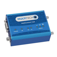
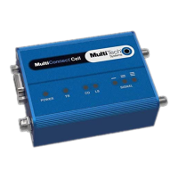
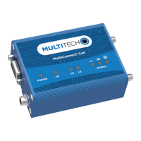
LED Descriptions
The top panel contains the following LEDs:
Power and Terminal Ready LEDs—The Power LED indicates that DC power is present and the TR LED blinks
when the unit is functioning normally.
Modem LEDs—Two modem LEDs indicate carrier detection and link status (for serial units only).
Prog. Signal LEDs—Three programmable signal LEDs can display the signal strength level of the wireless
connection if coded by the user.
LED Indicators
POWER Indicates presence of DC power when lit.
TR Terminal Ready. When lit, indicates connection to terminal emulation. When not lit,
indicates no terminal is present.
(for serial only)
CD Carrier Detect. Indicates established data connection when lit.
(for serial only)
PROG. SIGNAL These LEDs do not function by default and require the user to write code in order to
control them. If programmed, they display the strength of the cellular signal.
Note: The three PROG. SIGNAL LEDs can be controlled as follows:
GPIO2: Controls the LED with a single bar above it
GPIO3: Controls the LED with two bars above it
GPIO4: Controls the LED with three bars above it
For more information on using GPIO to control the LEDs, refer to the AT Command Guide.
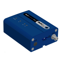
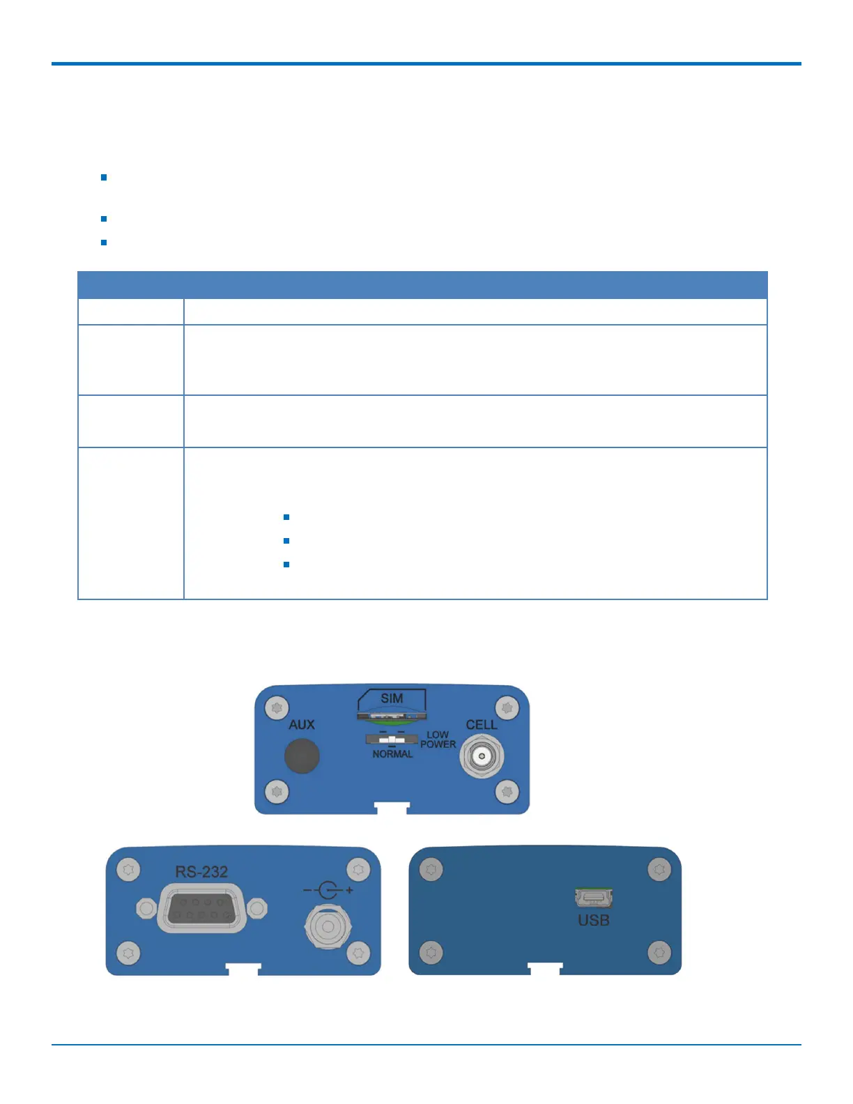
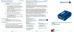
Side Panels
The device has connectors on either side. The figures that follow show the side panels.