3-2
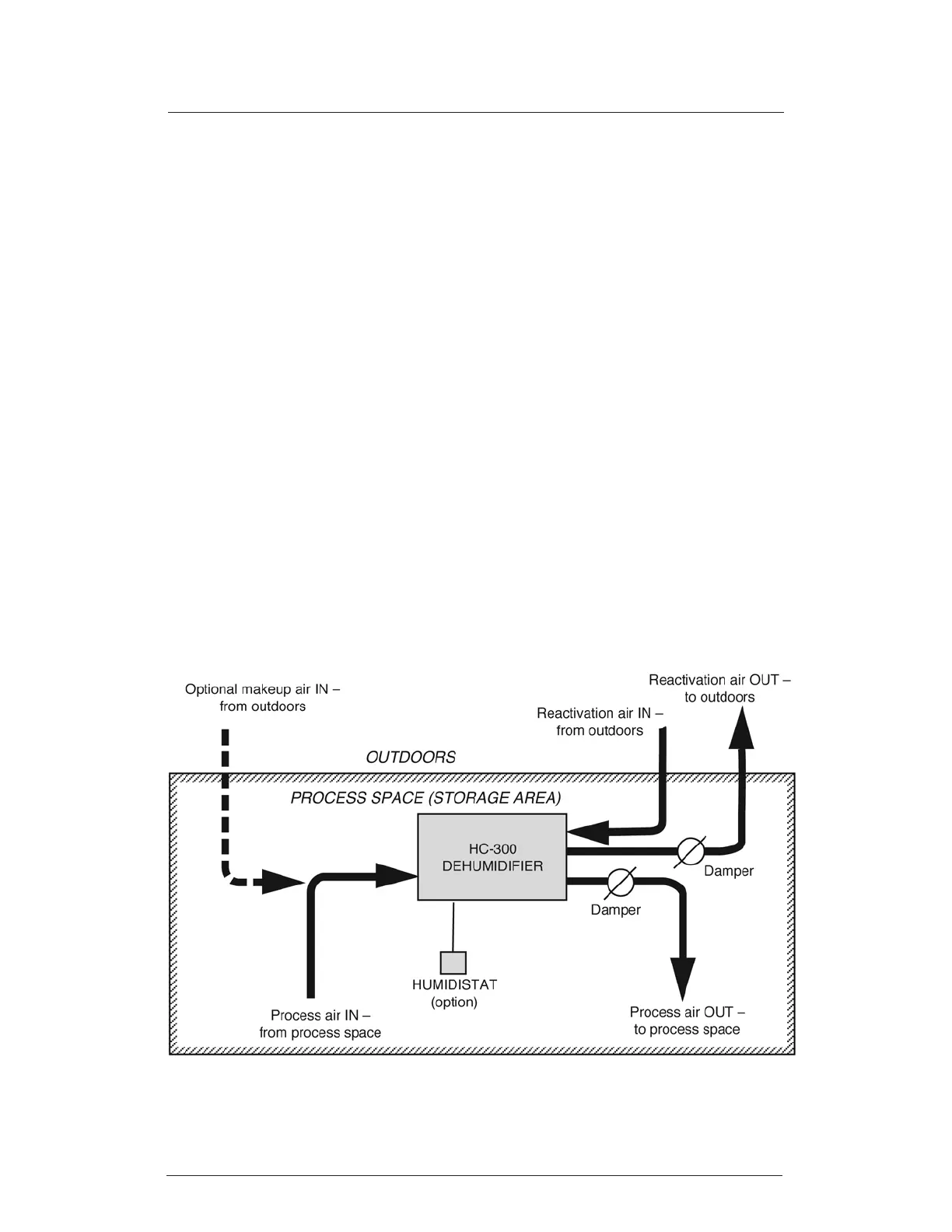
2. Figures 3-2, 3-3 and 3-4 show three different ways of installing the HC-300.
3. There are some simple rules for arranging the ductwork for the HC-300:
Process air intake Taken from the storage space
Process air outlet Vented to the storage space
Reactivation air inlet Taken from a separate space (not from storage space –
don’t use dehumidied air)
Reactivation air outlet Vented outdoors (air is very damp - don’t use for space
heating)
(Note – The reactivation air can also be taken from and returned to an indoor space
where the temperature and humidity levels are not important.)
4. Wherever the intake or outlet ducts open outdoors, protect them from the elements.
Install weather hoods and bird screens.
5. Do not locate the intake and outlet for the process air too close together. If possible,
allow a distance of at least 5 feet. Allow the same distance between the inlet and
outlet for the reactivation air.
6. Figure 3-4 shows the set-up if you are installing the HC-300 in a system with an
existing air-handling unit. Notice that both sides of the HC-300 are connected up-
stream of the air-handling unit.
FIGURE 3-2
HC-300 INSTALLED IN PROCESS SPACE