1-4
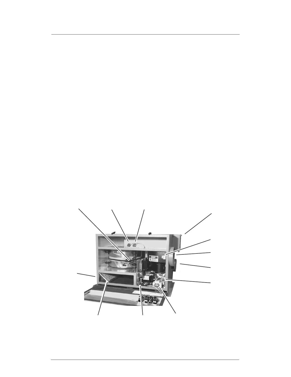
Circuit breaker
Drive motor and
belt tensioner
Reactivation fan
control board
Process air
inlet
Process
air blower
Process
air outlet
Temperature sensor
(TS01)
Temperature sensor
(TS02)
Solid state
power control
for heaters
(SSP1)
Process
air lter
FIGURE 1-4 - FRONT VIEW, COVER OPEN
located in the reactivation air stream after the wheel. This design allows reduced energy
consumption at low load levels.
The unit continues to run for a few minutes after the Auto/Off/Manual switch is turned off.
This “cool-down” cycle helps to protect the heating elements from overheating. During
the cycle, the reactivation blower continues to operate. The “cool-down” period is con-
trolled by a thermostat switch (TS02).
1.4 PROTECTIVE CIRCUITS
The HC-300 has several sensors and circuits which protect the machine and operator
from possible problems. A temperature switch (TS01) is located just downstream of the
heater. This sensor will tell the control circuits if the elements overheat (temperature
above 320°F). If this happens, the Fault indicator will light and the machine will stop. To
reset the machine, wait until the unit cools to normal temperature. Turn the Auto/Off/
Manual switch off, then on again.
The wiring for each heating element includes a fusible link. This link will open if the
element overheats. If this happens, the HC-300 will continue to operate, but will not
dehumidify the process air. To correct this, nd the cause of the overheat condition and
replace the fusible link.
If a blower motor is jammed, it will start to draw a large amount of electrical current. If
one of the motors detects this condition, that motor will shut itself down. The rest of the
unit will continue to operate, unless an overheat fault is triggered. The affected motor will
reset itself automatically.
Entrance for
power
connection
Reactivation
air inlet and
lter
Reactivation
air outlet