1-2
The next job is to move this moisture out of the wheel. As we said, the desiccant will give
up moisture when it is heated. When it is heated, and the moisture released, we say it
is “reactivated.” In the HC-300, a stream of “reactivation” air is taken from outside the
controlled space and heated using an electric heater. This heated air is forced through
the channels in the HoneyCombe
®
wheel. The desiccant releases the moisture into the
heated air stream. Finally, the damp reactivation air is vented outside. At this point, the
moisture has been moved from the storage room to the wheel, then from the wheel into
the outside air. The process is complete.
You may have noticed that, at one moment, we’re using the wheel to pick up moisture,
and a moment later, we’re heating the wheel to drive off the moisture. In the HC-300,
both actions are happening at the same time, on different sections of the wheel.
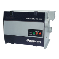
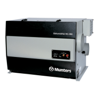
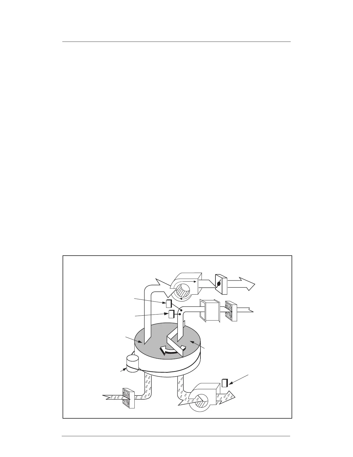
1.2 ABOUT THE HC-300
This is a simplied explanation of the operating principle. Figure 1-2 shows how we put
this principle to work in the HC-300. You can still see the parts we discussed in the last
Figure – the HoneyCombe
®
wheel, process air stream and reactivation air stream. We
have also added a number of other parts:
• Two sets of seals to separate the two streams of air (damp process air and the
heated reactivation air)
• Blower, damper and lter for the process air
• Blower and lter for the reactivation air
• Temperature sensors
• Electric heating elements for the reactivation air
FIGURE 1-2 - HC-300 IN OPERATION
Desiccant wheel
Heater
Filter
Process
air outlet
(dry air)
Blower
Drive
motor
Process air inlet
(moist)
Reactivation
blower
Reactivation
air outlet
(moist)
Temperature
sensor
TS02
Reactivation
sector of wheel
Process air
damper
Process
sector of wheel
Filter
Overheating
sensor
TS01
Reactivation air
temperature sensor
TSE1