1-3
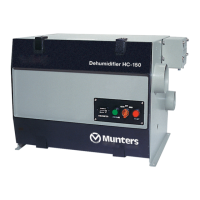
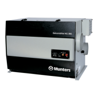
Figures 1-3 and 1-4 show some additional parts on the HC-300 unit. The HoneyCombe
®
wheel is turned by a small drive motor and a toothed belt. A spring-type tensioner
automatically adjusts the belt tension.
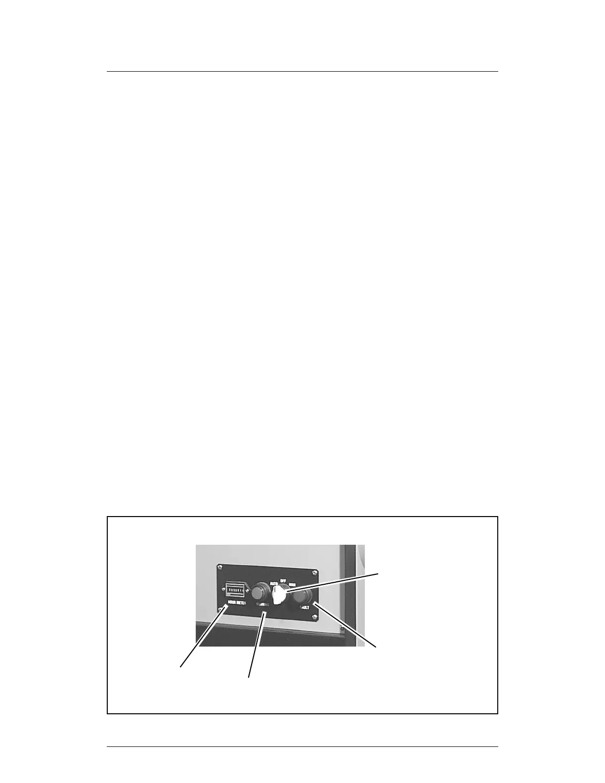
1.3 CONTROLS AND INDICATORS
The unit has four indicators and controls on the control panel:
Auto/Off/Manual switch:
Auto position (amber) This indicator is on whenever the HC-300 is operating in the
automatic mode. The unit is switched on and off by a remote
humidistat.
Off position (amber) This indicator is on when the AC power to the unit is on, and it
is not running (not set to Auto or Manual). (On shut-down, the
heating elements will switch off. The reactivation blower will
continue to run to cool down the unit. Once cooled down, the
unit will become inactive.)
Manual position (amber) This indicator is on whenever the HC-300 is operating in the
manual mode. The unit runs continuously until it is switched
off.
Running light (green) This indicator is on whenever the unit is running (the Auto/Off/
Manual switch is in the Manual position, or the switch is in the
Auto position and the humidistat contacts are closed).
Fault light (red) This indicator is normally off. This light turns on when the unit
overheats. See the section on “Troubleshooting.”
Time meter This indicator shows how many hours the unit has operated.
The control system uses a number of sensors and controllers to supervise the activity of
the HC-300. A Solid State Power Controller (SSP1) turns the heating elements on and
off. This controller responds to a signal from a temperature sensor (TSE1) which is
FIGURE 1-3
CONTROLS AND INDICATORS
Running light
Time meter
Fault light
Auto/Off/Manual switch