5 Operation
5.1 Controlpanel
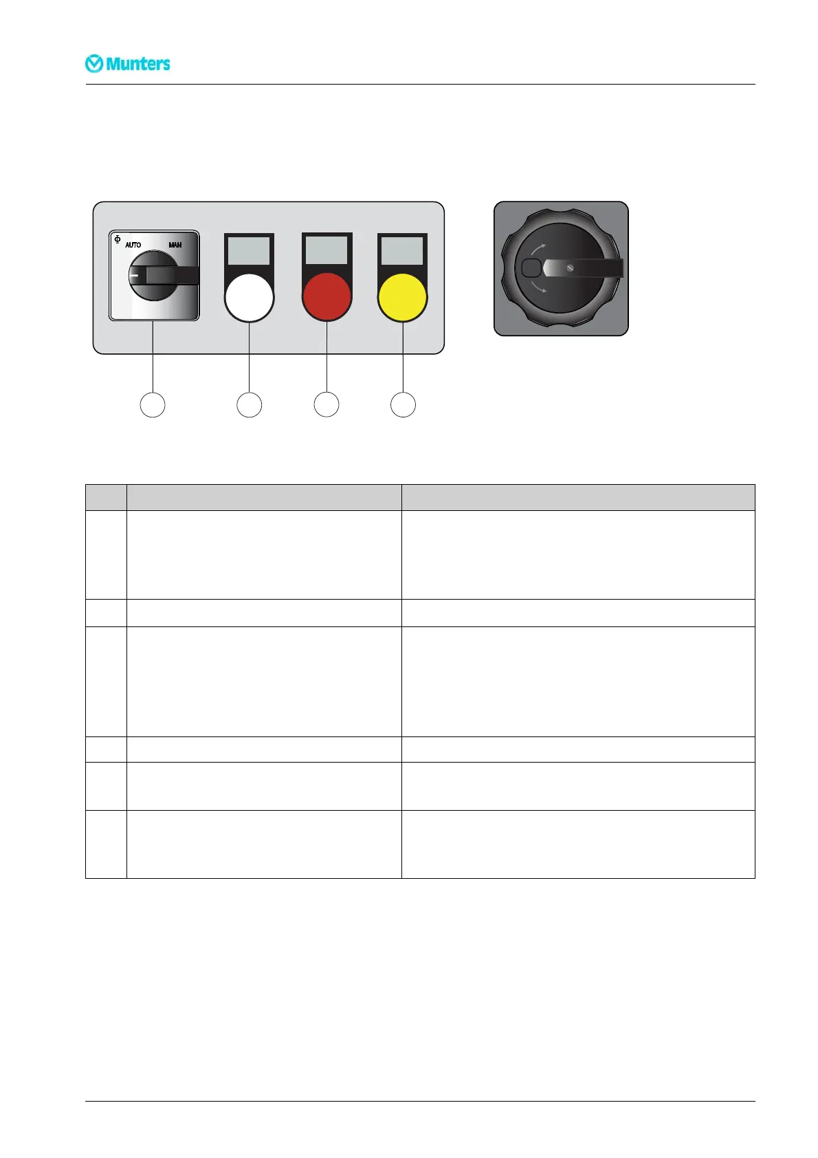
RUN
SERVICE
ALARM
1
2
34
0
Figur e 5.1 Control panel
o
OFF
o
1
ON
OFF
SIEMENS
Figure 5.2 Main power switch
Item Switch/Indicator Function
Main power switch(see
Figure 5.2
) Whenthe mainpowerswitchisin position0,the unitisnotpowered
beyondtheswitch.
Whenthe mainpowerswitchisin position1,the dehumidifiercanbe
started.
Controlandregulationsystem (HMI) See thesupplementfor informationonHMIoperation.
1 Mode switch Whenthe modeswitchisin position MAN,thedehumidifierruns
continuously(fullcapacity). Thereis abriefdelay beforetheunitstarts.
Whenthe modeswitchisin positionAUTO,thedehumidifieris regulated
byaninternaladjustablehumiditylevelsetpoint,orviaan externalinput
signal.
2 Whitelamp (RUN) Lightswhenone ofthe fans isrunning.
3 Red lamp (ALARM) Illuminateswithasteady glow whenan alarmhasbeen triggered. Check
whichalarm has been triggered.
4 Yellow lamp(SERVICE) Lightswhena filterchangeis required,orwhen the dehumidifierhas
reachedthenumber ofoperatinghours orthedateat whichmainte-
nanceshould be carriedout,seesection
6.5, Service indicator lamp
.
Table 5.1 Control panel functions
34
Operation
190TEN–1089–G1412