© Munters AB, 2016 16
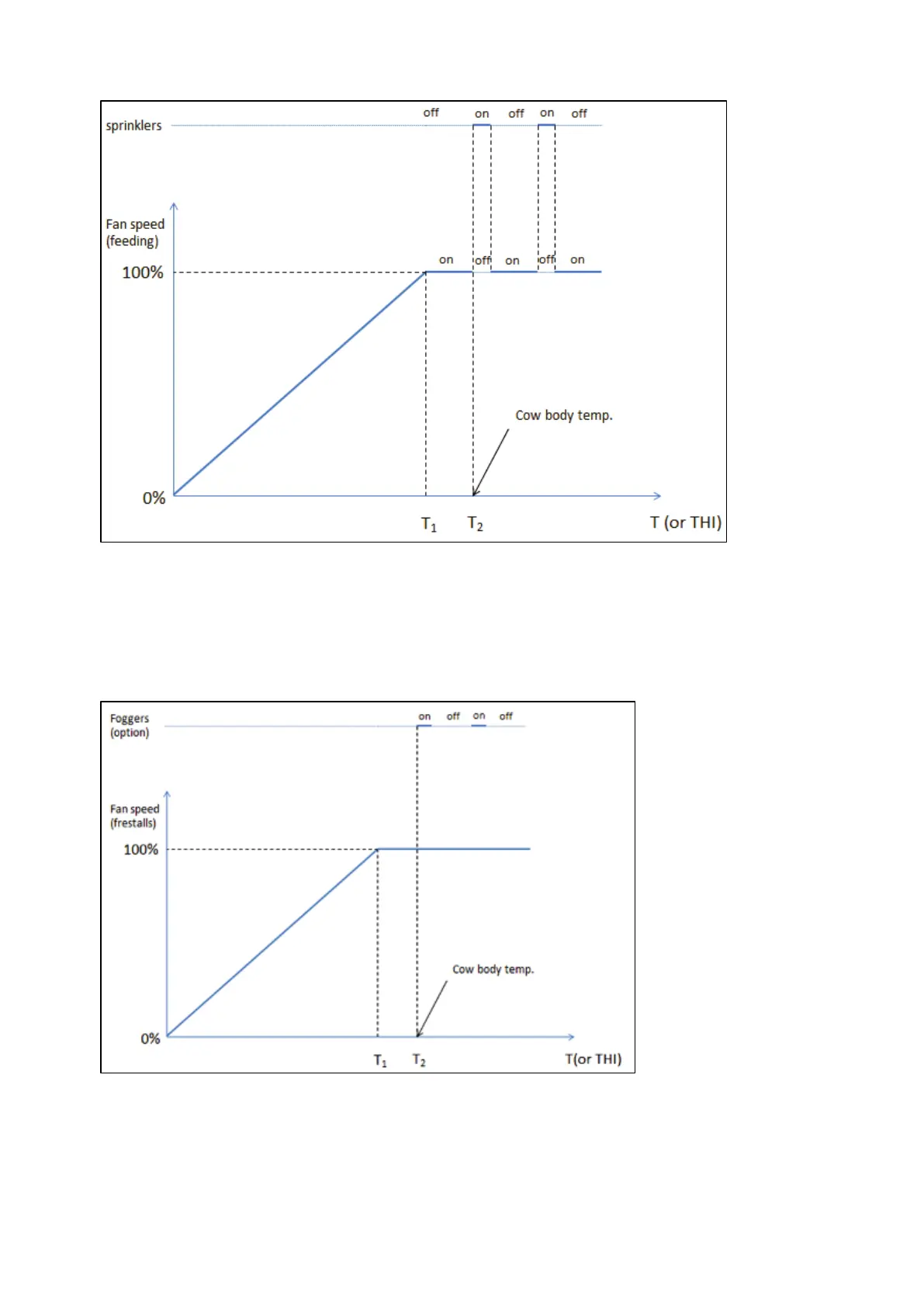
Figure 3: Graph demonstrating Zone 1 ventilation and soaking
NOTE When soakers operate, Fan1 is disabled.
•
The fans go from 0 to 100% based on the Munters Drive Temp Diff and Temp Band
parameters (Munters Drive fans setup).
•
Soakers begin operating based on the Temp Diff On parameter (Fogger and soaker setup)
Figure 4: Graph demonstrating Zone 2/3 ventilation and fogging
•
The fans go from 0 to 100% based on the Munters Drive Temp Diff and Temp Band
parameters (Munters Drive fans setup).
•
Foggers begin operating based on the Temp Diff On parameter (Fogger and soaker setup)