Operation
User manual 59719_hdb_en_12 40 / 65
7 Operation
NOTE
After writing an application-specific tag in the IO-Link hub, the hub briefly
interrupts the IO-Link connection if the text is not the same as the text stored
in the hub.
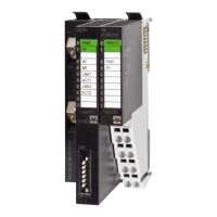
7.1 LED indication
The MVP12 modules are equipped with the following separate LED indicators:
LED indication for inputs/outputs
LED indication for IO-Link and US sensor supply
LED indication for actuator supply UA (Class B only)
Indication takes place by means of static lighting or flashing of the LEDs.
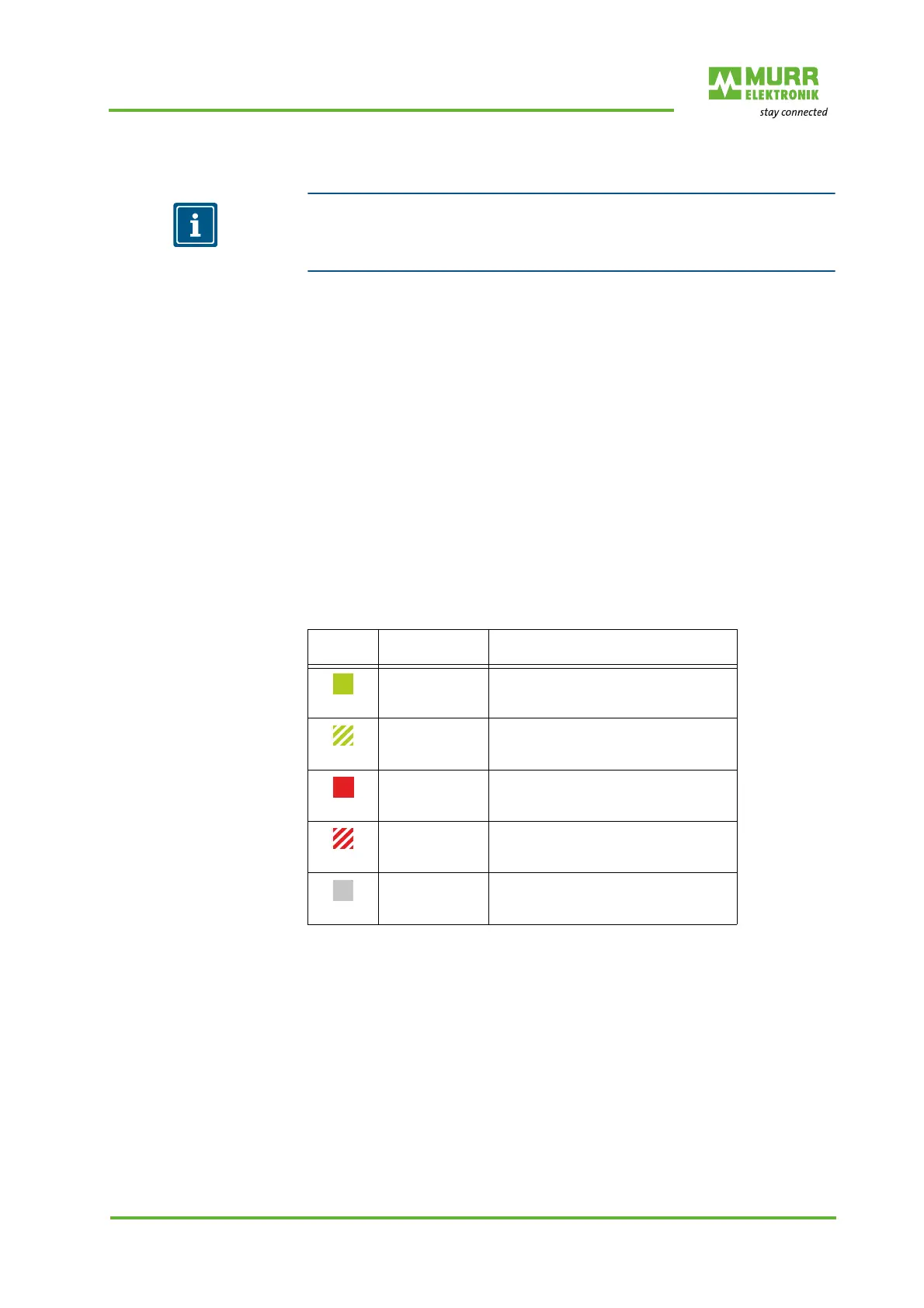
7.1.1 LED indication US and IO-Link
The device has a combined LED for the IO-Link status and the status of the
US sensor supply. The IO-Link status is mapped by the green LED chip, and
the US status by the red LED chip.
This can give rise to a mixture of green and red flashing codes (in case of over-
lap orange flashing code).
Combined LED indica-
tion IO-Link and US
Tab. 7-1: Indication IO-Link and US
LED in-
dication
LED state Description
Green
Permanently on IO-Link not in OPERATE status,
no cyclic data communication;
sensor power supply OK
Green
Flashing
1 Hz
IO-Link in OPERATE status,
cyclic data communication;
sensor power supply OK
Red
Permanently on Short circuit DO, temperature warning
etc.
Red
Flashing
1 Hz
Communication error IO-Link
Off
Device off, no IO-Link connection
 Loading...