24
M1.2.HB240-HB240M.NLFREN 21112017
FR
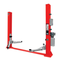
9� Branchez les câbles (g. 10).
1. Montez le boîtier de commande sur la colonne avec le bloc d’alimentation.
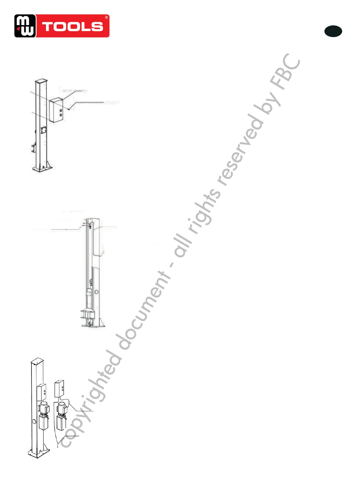
2. Fixez l’interrupteur de n de course sur la colonne avec le bloc d’alimentation (g. 11).
3. Branchez l’électrovalve et le câble du moteur (g. 12).
Step9: Connect wires.
1. Mount the control box on to the power side post.
2. Fix the limit switch into the power side post.
3. Connect the wire of solenoid valve and motor wire
Fig� 10
Boîtier de commande
Vis moletée
Raccord Hex M4*26
Step9: Connect wires.
1. Mount the control box on to the power side post.
2. Fix the limit switch into the power side post.
3. Connect the wire of solenoid valve and motor wire
Fig� 11
Interrupteur de n de course
Vis M5*12
Buse letée
Raccorder avec le câble
venant du boîtier de
commande
Step9: Connect wires.
1. Mount the control box on to the power side post.
2. Fix the limit switch into the power side post.
3. Connect the wire of solenoid valve and motor wire
Fig� 12
Branchez le câble du moteur
sur les bornes dans le boîtier
de commande
Câble d’alimentation
copyrighted document - all rights reserved by FBC
 Loading...