35
M1.2.HB240-HB240M.NLFREN 21112017
EN
3�2 Precautions for installation
• Make sure the two posts stand paralleled and are vertical to the ground. No slanting.
• Joints of oil hoses and steel cables must be rmly connected in order to avoid the looseness of steel cables and leakage of
oil hoses.
• All bolts should be rmly screwed up.
• Do not place any vehicle on the lift in the case of trial running.
3�3 Installation
Fig� 3
1� Remove the packaging, take out the carton for accessories and cover plate.
2� Firstly, put something supporting between the two posts or suspend one of the posts by a crane and then remove the bolts
on the package.
Attention! Please pay special attention not to let the post fall down for it may cause casualty or
bring damages to the accessories xed in the post.
3� When the rst post has been taken away, place something supporter under the second post and then remove the bolts on
the package.
4� Fix the standing position for the two posts (see chapter 9, oor plan).
1. Unfold the package and decide on which post the power unit will be mounted.
2. Draw an outline of the base plate on the ground with chalk and ascertain the position for the post.
5� Erect the posts, power side post rst and then the other post.
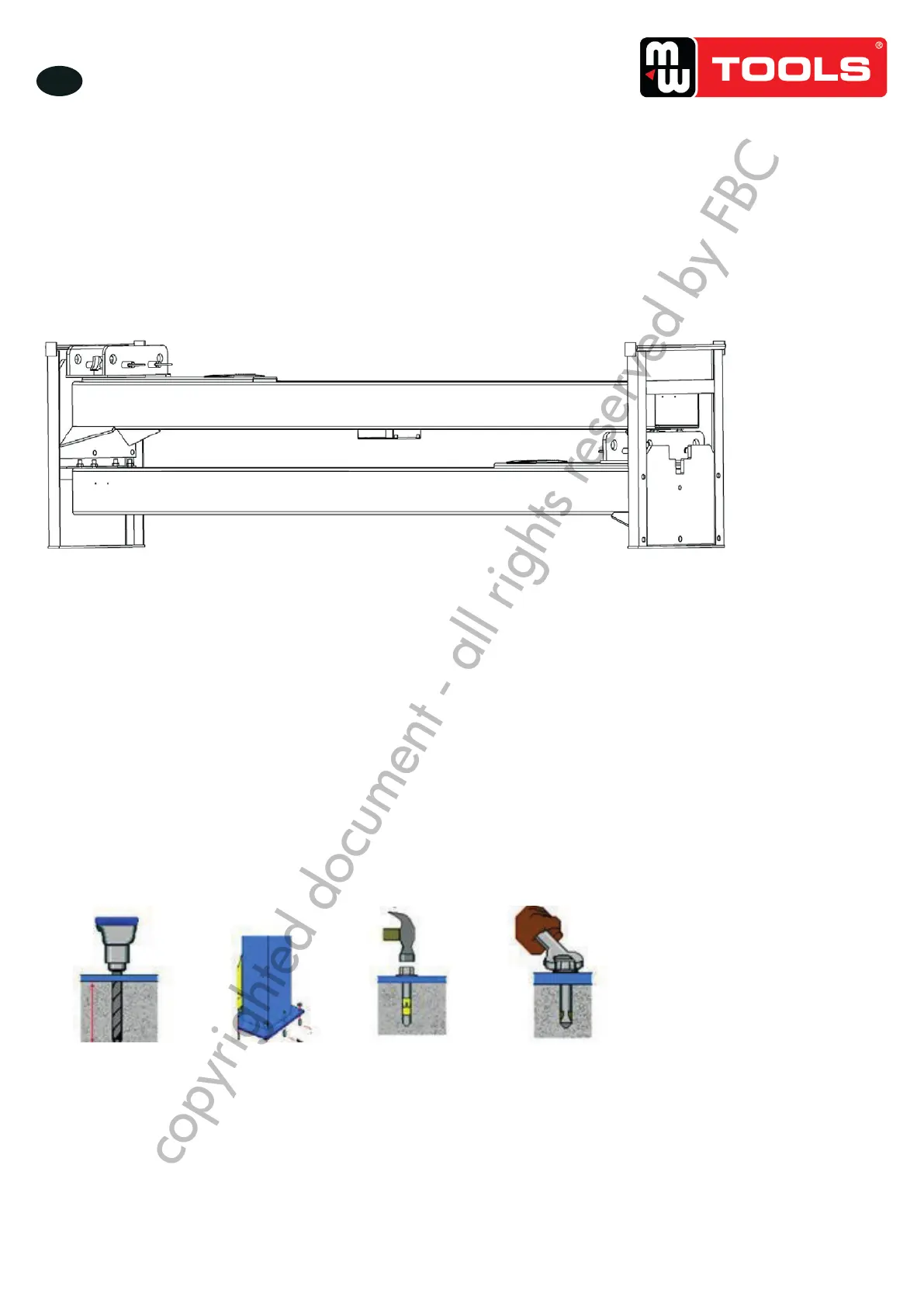
1. Drill anchor holes for expansion bolts on the ground with an electrical drill. Make sure to drill vertically (g 3).
2. After holes have been drilled, remove thoroughly the debris and dust in them and ascertain that the posts stay upon the
circle previously drawn by chalk (g 4,5,6).
INSTALLATION INSCRUCTIONS
3.1 Preparations before installation
3.1.1 Tools and equipments needed
Appropriate lifting equipment
Anti-abrasion hydraulic oil.
Rotary Hammer Drill with 3/4’’ drill bit.
Chalk and tape measure, magnetic plump, 8 metersФ15 level pipe.
Sockets and open wrenches, a set of inside hex wrenches, cross and straight screw drivers.
Hammer, 4pounds,
sharp nose pliers, Ф17,Ф19,Ф22 socket spanners。
3.1.2 List for parts checking ---Annex 1(Packing list)
Unfold the package and check if any parts missed as per Annex 1. Do not hesitate to contact us in case any parts missed, but if
you do not contact us and insist installing upon the lack of some parts, well as our dealers will not bear any responsibility for this
and will charge for any parts subsequently demanded by the buyer.
3.1.3 Ground conditions
The lift should be fixed on a smooth and solid concrete ground with its strength more than 3000psi, tolerance of flatness less
than 5mm and minimum thickness of 200mm. In addition, newly built concrete ground must undergo more than 28days’ cure
and reinforcement.
3.2 Precautions for installation
3.2.1 Make sure the two posts stand paralleled and are vertical to the ground. No slanting.
3.2.2 Joints of oil hose and steel cable must be firmly connected in order to avoid the looseness of steel cable and leakage of oil
hose.
3.2.3 All bolts should be firmly screwed up.
3.2.4 Do not place any vehicle on the lift in the case of trial running.
3.3 Installation
Step 1: Remove the packaging, take out the carton for accessories and cover plate.
Step 2: Firstly, put something supporting between the two posts or suspend one of the posts by a crane and then remove the
bolts on the package.
Attention:Please pay special attention not to let the post fall down for it may cause casualty or bring damages to the accessories
fixed in the post.
Step3: When the first post has been taken away, place something supporter under the second post and then remove the bolts
on the package.
Step 4: Fix the standing position for the two posts. (See Annex 3, floor plan)
1. Unfold the package and decide on which post the power unit will be mounted.
2. Draw an outline of the base pla te on t he ground with chalk and ascertain the position for the post.
Step 5: Erect the posts, power side post first and then the other post.
1.Drill anchor holes for expansion bolts on the ground with an electri cal drill . Make sure to drill vertically. (Fig 3)
2.After holes have been drilled, remove thoroughl y the debris and dust in them and ascertain that the posts stay upon the circle
previously drawn by chal k. (Fig 4,5,6)
Step6: Connect steel cables. (Fig 7)
1. Route and fix according to the following diagram of steel cable connection.
2. Raise carriages on both sides approximately 800mm above the ground. Carr i ages must be on the same height from the floor.
3. Make sure that t he mechanical safety locks in each post are fully engaged before attempting to rout e cables.
4. After the cable being fixed, adjust and make the cable at both sides be wit h the same tightness whi ch could be judged by the
sound emitted during lifting process. Make judge and adjustment after trial running.
5. Grease after being fixed. (It is a must.)
Fig� 3 Fig� 4 Fig� 5 Fig� 6
copyrighted document - all rights reserved by FBC