Adjustments and Status LEDs 4-11
Rev. 9-09-16 Part #C-00084
www.NabcoEntrances.com Magnum 4A Control Wiring and Adjustment Manual
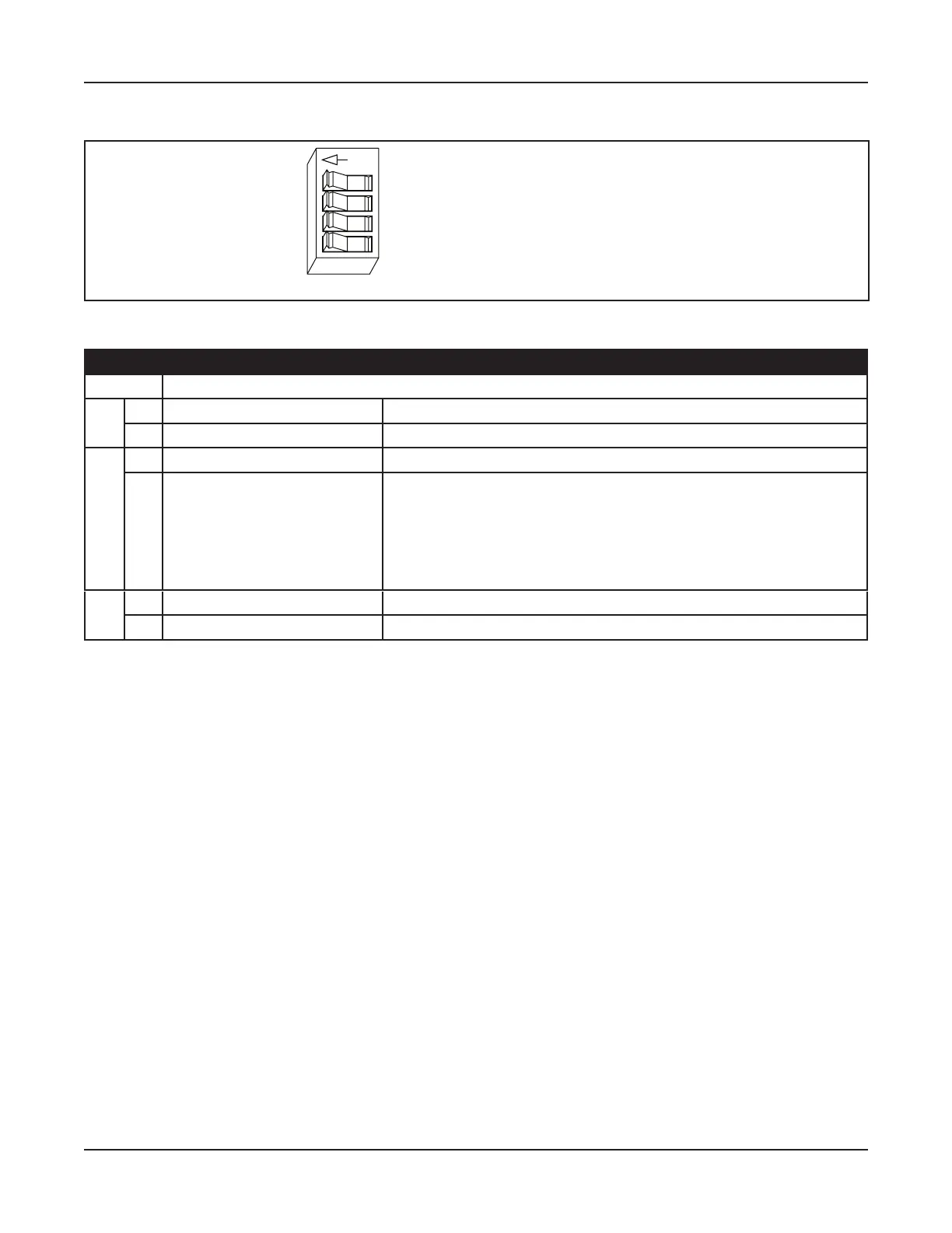
Figure 4-3 Dip Switch (Displayed in ON position)
DN 0561
OFF
SWITCHES SHOWN IN “ON” POSITION
1 Not Used
2 OFF: Closed Loop Safety / ON: Open Loop Safety
3 OFF: Push-N-Go active / ON: Push-N-Go Inactive
4 OFF: Sequential Mode / ON: Timer Mode
Table 4-1 Dip Switch Settings
Switch Adjustment
1 Not Used
On Open Loop Safety X Safety triggered when contact is closed by a Switch or Sensor
Off X * Safety triggered when contact is opened by a Switch or Sensor
On X
Off X
active in any position.
X
X Door opens when pushed.
• Switch 4 must be turned “On” for door to time out and close.
4 On Timer Mode X Door will open, time out and then close.
Off Sequential Mode X One activation opens door, second activation closes door.
► Upper Position
• Used for Low Energy Operators.
• Motor power is reduced to approximate ANSI 156.19 Low Energy Standards.
► Lower Position
• Used for Standard Full Automatic Operators.
•
• Motor power is increased to approximate ANSI 156.10 Standards.
It is recommended to set door speeds as slow as the owner will accept, and no more than the applicable
ANSI Standards. Use a stopwatch for assistance. Please see .
► a parameter.
► a parameter.
 Loading...
