Wiring Diagrams (General) 7-19
Rev. 9-09-16 Part #C-00084
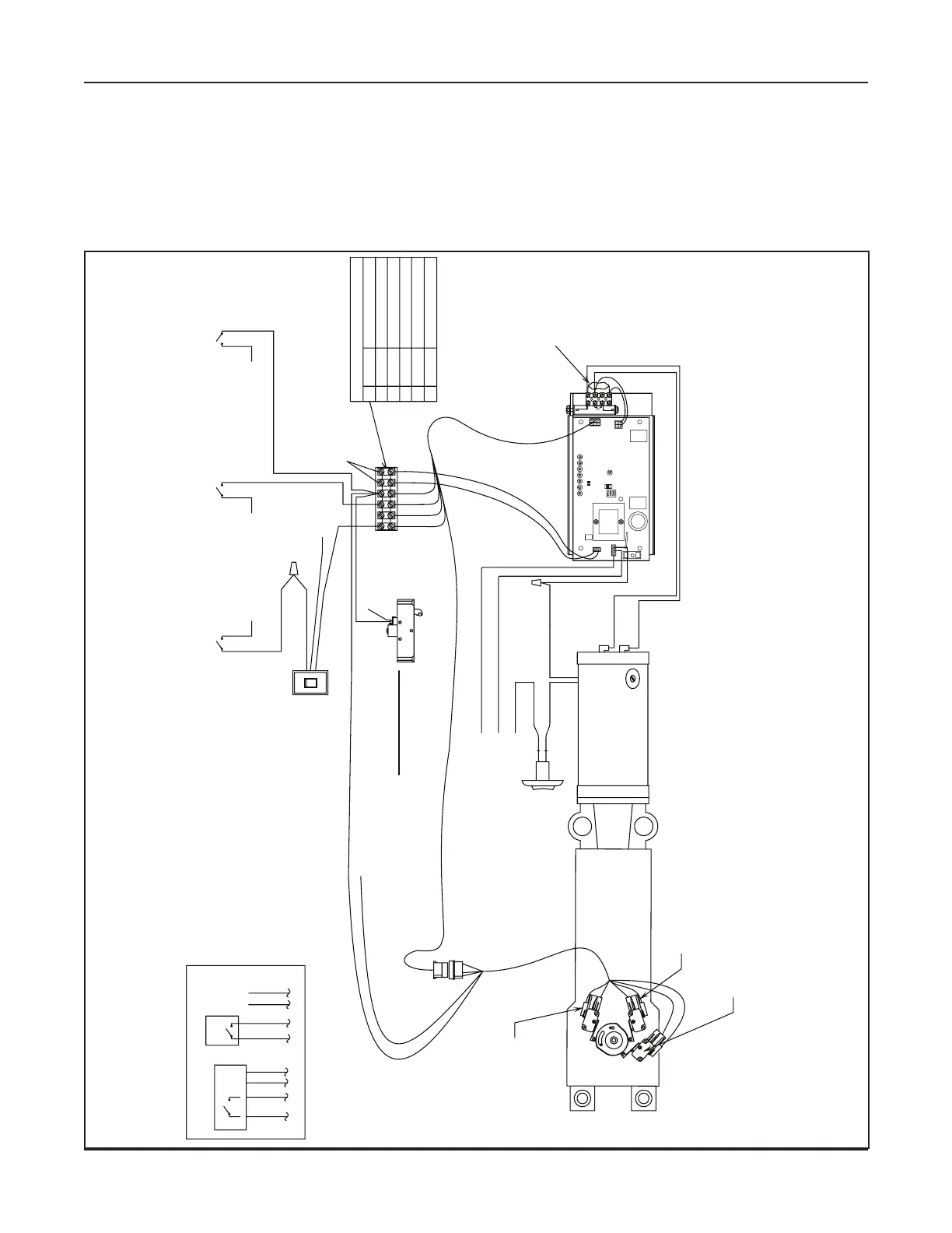
www.NabcoEntrances.com Magnum 4A Control Wiring and Adjustment Manual
DN 0567
Off
H
o
l
d
O
p
e
n
O
n
Off
White
Black
Red
Activation
Safety with Lockout
during door swing
Continuous Safety
24 VAC AUX Output
for sensors
TERMINAL BLOCK
#1 BROWN
#2 ORANGE
#3 VIOLET
#4 WHITE
#5 RED
#6 BLACK
24VAC NEUTRAL
24VAC HOT
CONTINUOUS SAFETY
SAFETY WITH LOCKOUT
24VAC COMMON
ACTIVATION
Ground
Black(Hot)
Black
Black
White (Neutral)
Part # 21-9934
300/400/500 Harness
for Magnum Board
Red: Comm, Blue: N.C.
C.
Black
Brown
Common
N.O.
Device
Not Used
Typical
Mat or
Wall Switch
24 VAC
Input
Typical Sensor
Device
If Rocker Switch is not Required
Connect the Activation Signals to
Terminals 5 and 6 Directly
Part # 10-3528
RS-12 Rocker Switch
Red
Red
Part # 11- 0941
Panic Latch Kit
When the unit has Panic Breakout feature,
Breakout Limit Switch Signal and/or Panic Latch Signal
MUST be connected to Continuous Safety input,
Terminal Block #3 
Breakout Limit Switch: N.O.
(Black and Brown)
ch
Part # 22-10065
Harness Assy
for Single
Back Check Limit Switch
BROWN
BLACK
RED
WHITE
VIOLET
ORANGE
Ter
#5
to Te rminal
#5 (red)
to Te rminal
#5 (red)
to Te rminal
#5 (red)
to Te rminal
#5 (red)
to Te rminal
#5 (red)
Panic Latch must be flipped.
arrow marked "EXT" points into the building.
(Contacts must close when door is broken out)
to Te rminal
#5 (red)
123456
ON/OFF
ROCKER
SWITCH
120 VAC
Part # 12-13166
Motor Fuse
(GT300, 400, 500)
LED
TRANSFORMER
O
F
F
12
AU
X
PWR
4
J2
3
J5
AC IN
F2
SW
2
SW
1
F1
RELAY
RELAY
J4
TDAS
SIGNAL
INPU
T
TDPG
LCHK
CLOS
E
Fuse 1: 0.5
A 24 VA
C
STOP
OPEN
BCHK
CURRENT
LIMIT
MOTO
J1
R2
8
MAGNUM 4A
R
Fuse 2: 5
A
120/240
Capacitor
MO
V
 Loading...
